Today I’m proceeding with the elevator balance weights and locating them on the elevators.
In the picture below, I have the balance weight assembly roughly located on the elevator. You can also note that I previously made 3 vertical black lines. These black lines indicate the spacing of the 3 structural screws (AN525-10R7) which attach the balance weight assembly to the elevator.
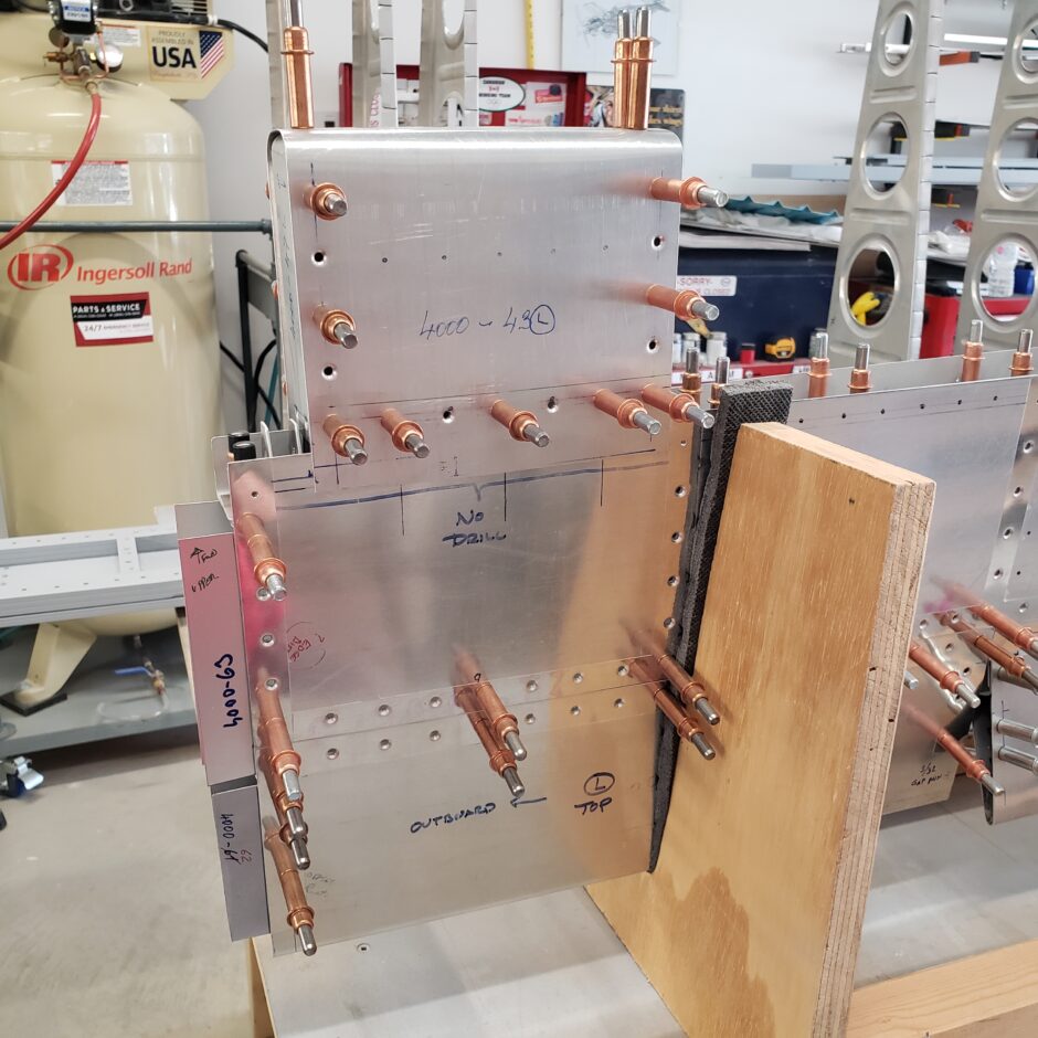
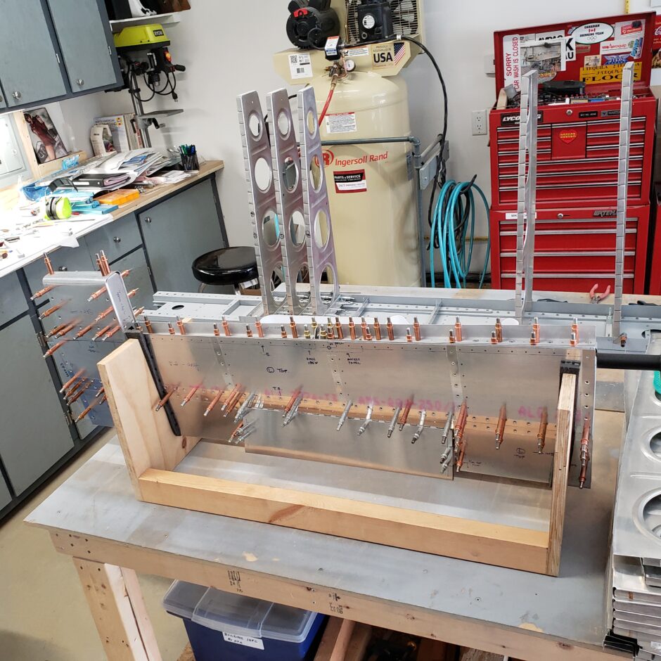
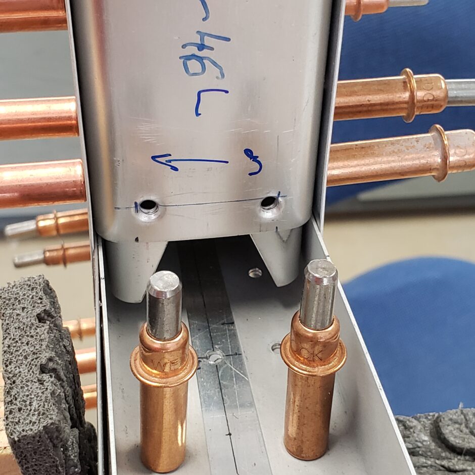
One interesting design feature of the balance weight assembly is how the stiffeners are angled, as shown below. In the following picture, you can see that this provides access on the hinge side of the balance weight assembly for the elevator hinge bolt nut.
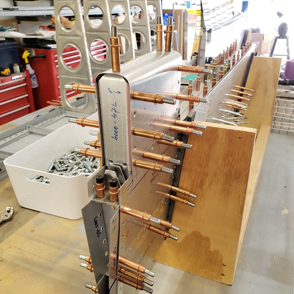
Before I can drill the balance weight attaching screw holes, the assembly also needs to be centered in the cutout for the weight in the horizontal stabilizer.
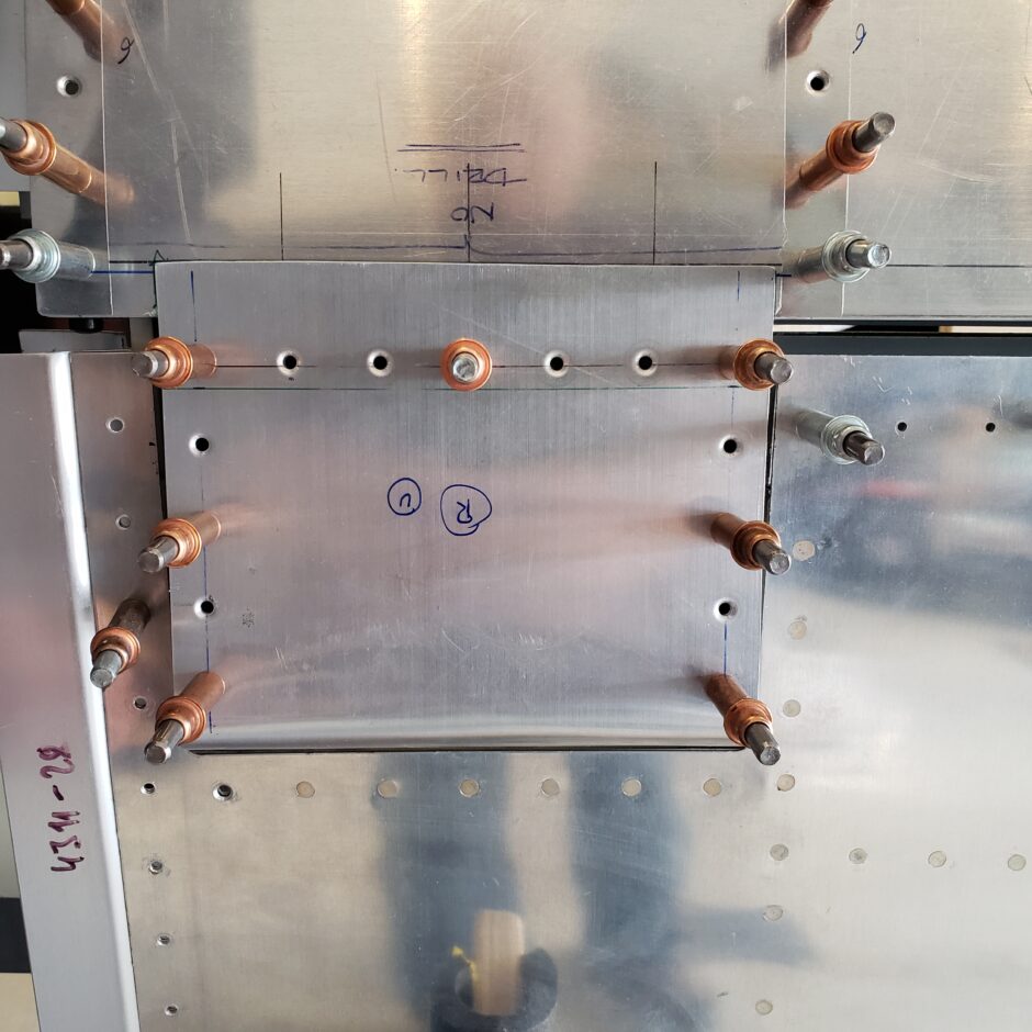
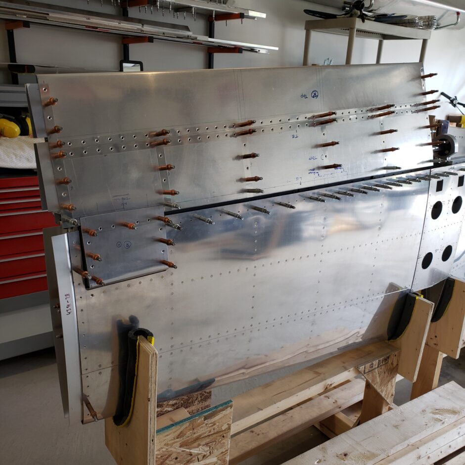
Once I was finally happy with locating the balance weight on the elevator in relation to the opening in the horizontal stabilizer, and lots of checking of the measurements…I finally drilled.
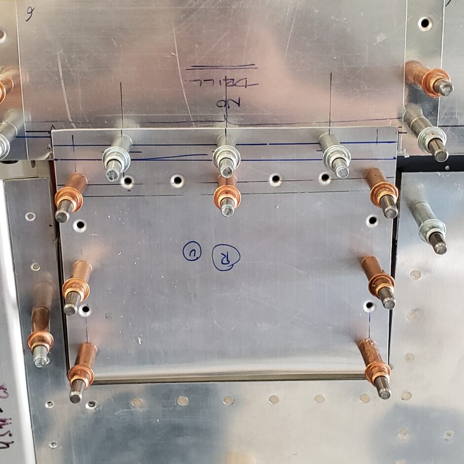
After locating the pilot holes I upsized the holes to 3/16 to accommodate the #10 screws.
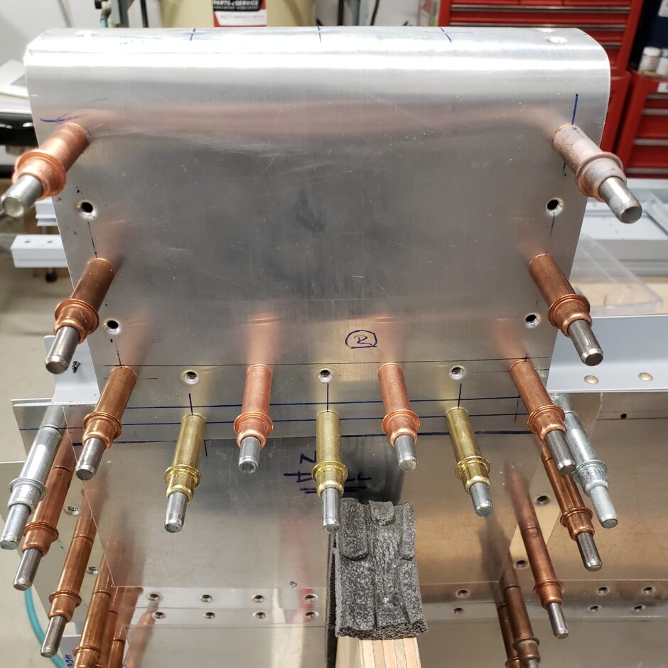
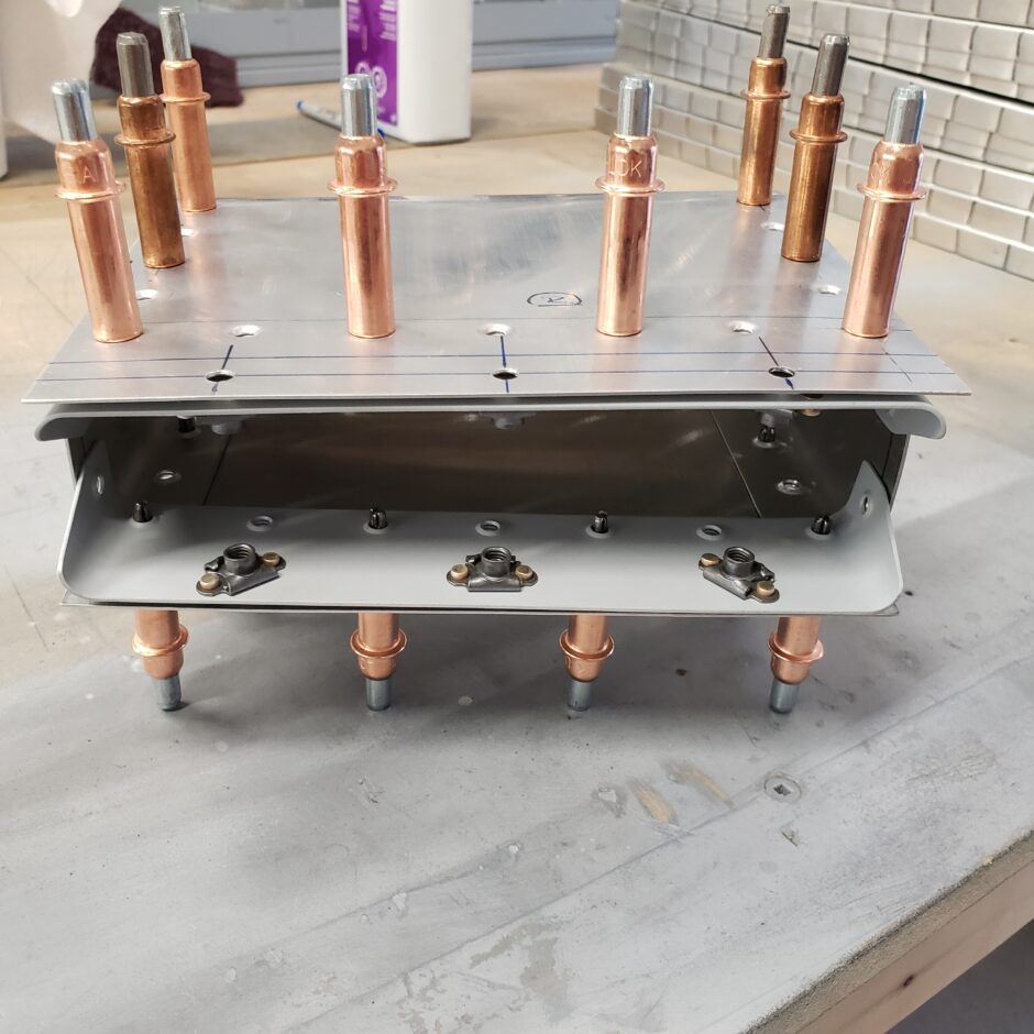
Once again, the weight assemblies came off and I removed the spacers and aft structural pieces, as I needed to clean up the edges, surface prep/prime and then added nutplates for the screws.
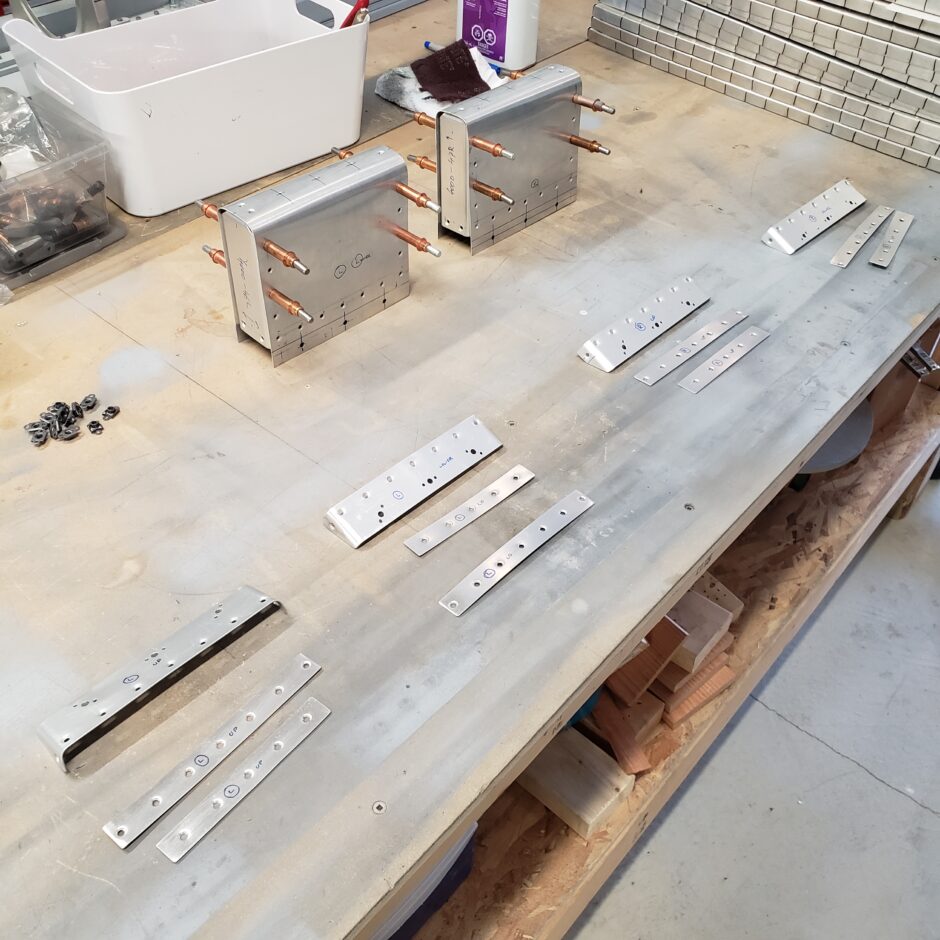
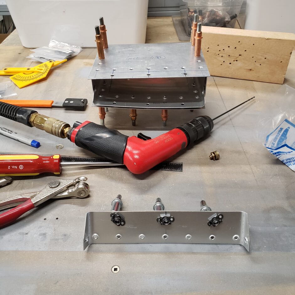
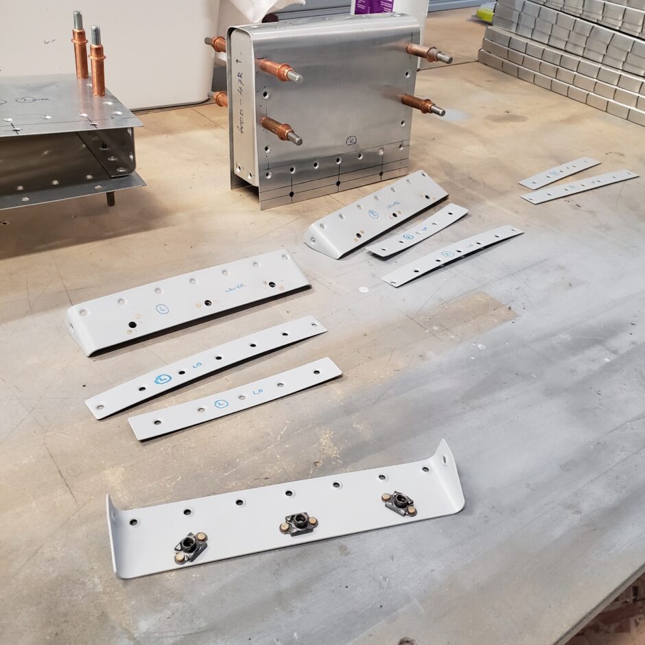
The balance weight assemblies are about as far as I can go on them for now. The next task on deck is to fit the elevator leading edges.
Please comment. I love to hear from my readers. Thanks again for coming along for this ride, you make my work worthwhile.
Leave a Reply