In this post, I’m finally arriving to a huge milestone where I’m finally mating the elevators to the horizontal stabilizer. Again, in this post, this process wasn’t accomplished in an afternoon. It took me the better part of 2 months of working on and off trying to stay motivated through all the filing needed to complete this task. No word of a lie, this was a shit ton of work to do, but in the end it’s been so worth it.
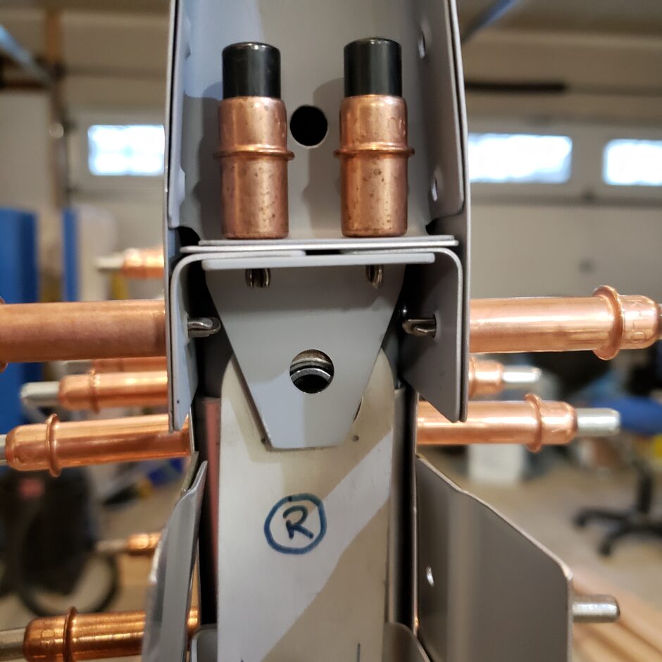
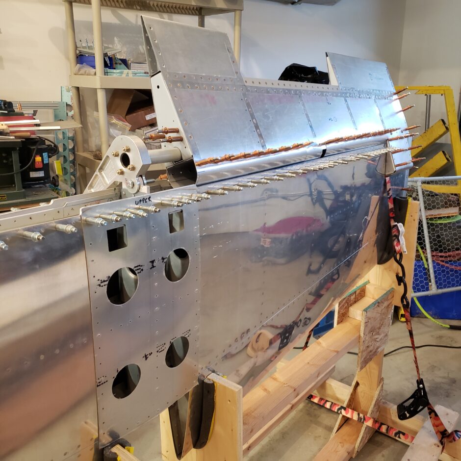
The starting point here, as you will see below is that the hinges don’t line up. The reason for this is because the trailing edge of the horizontal stabilizer is too long. The trailing edge of the stab is formed by the upper and lower skins to form a cavity. As these skins are long, and as the leading edge of the elevators sit within the trailing edge cavity, the result is the hinges don’t line up to be able to get the bolts in.
Below is the tip hinge of the right elevator.
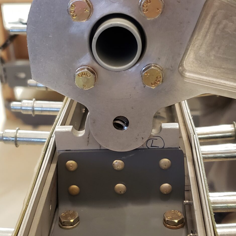
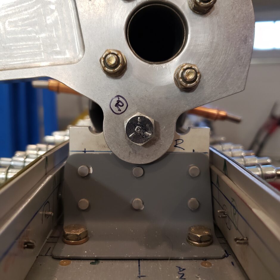
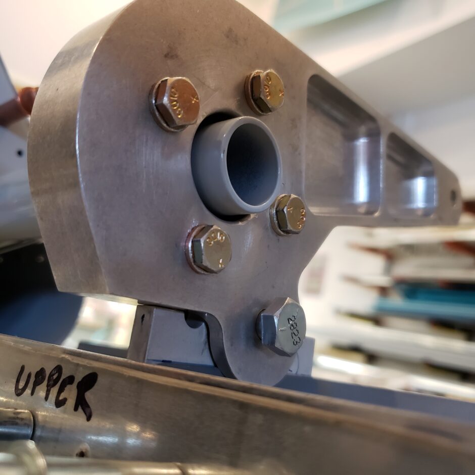
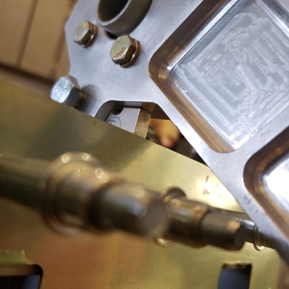
Here is the center hinge and bellcrank assembly. In this picture, also note the flat sides on the lower part of the hinge. These are the elevator up and down stops. If you look at the bellcrank, the travel limits (30 degrees up and 20 degrees down) are machined right into the bellcrank. I’ll get into this a bit later. First I need to get the bolts to fit.
The trimming began with marking the first of many cut lines to trim off the excess horizontal stabilizer trailing edge material.
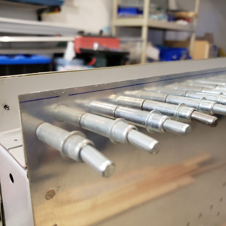
After the cut line is identified, it’s time to get down to filing.
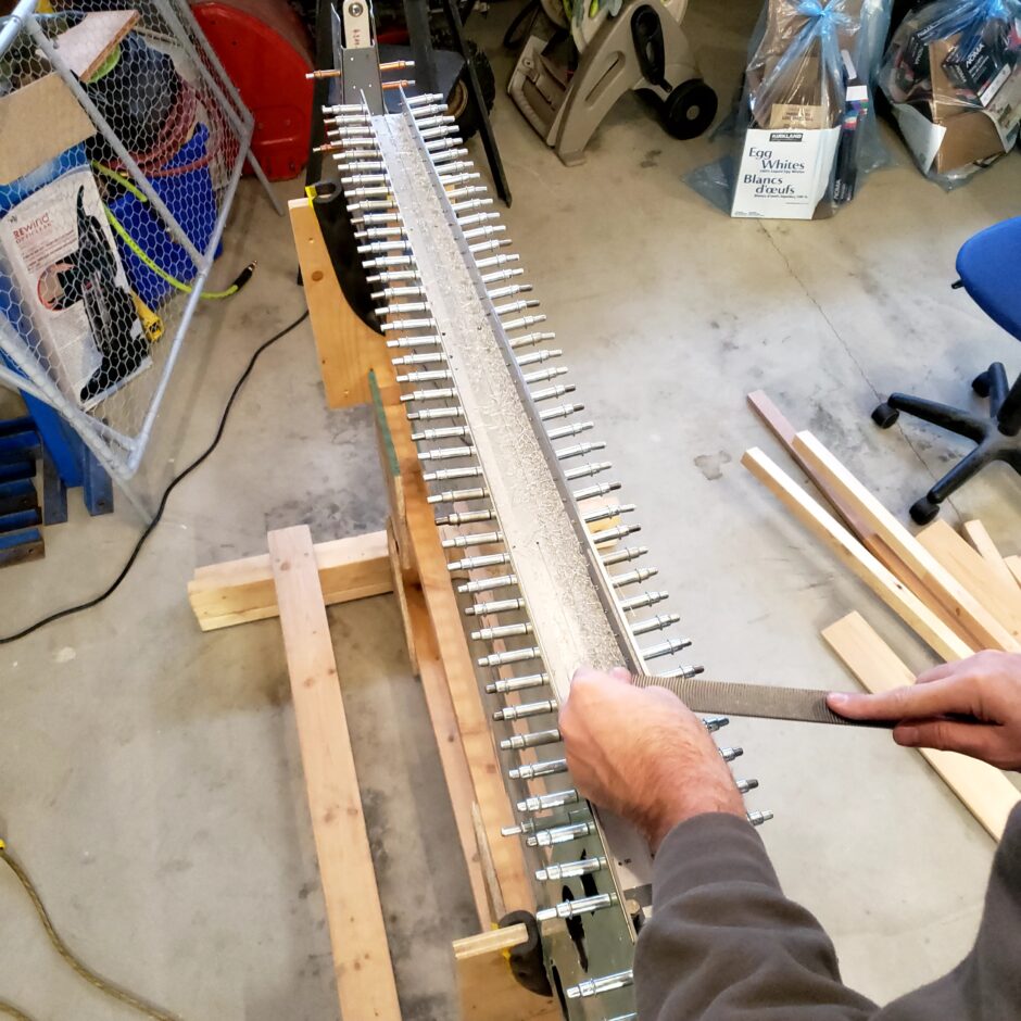
Lots of filings!!
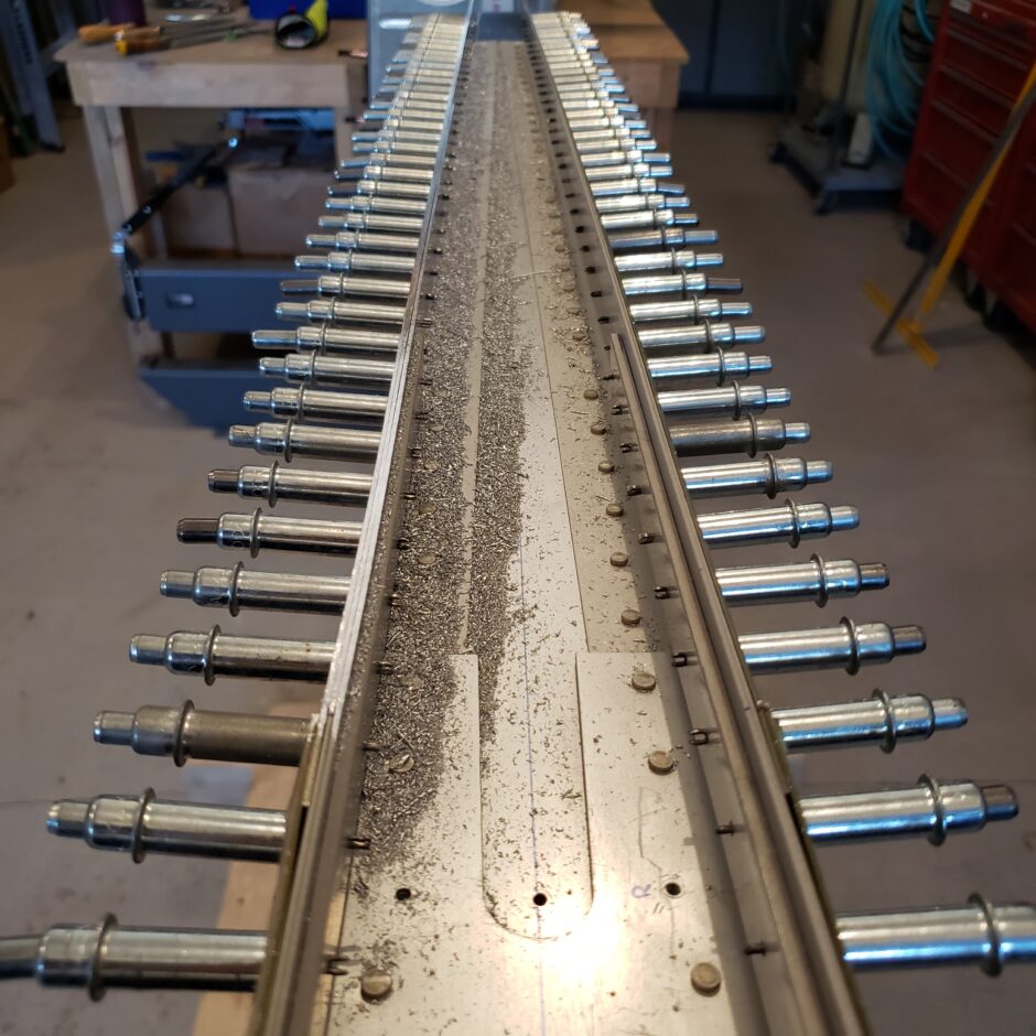
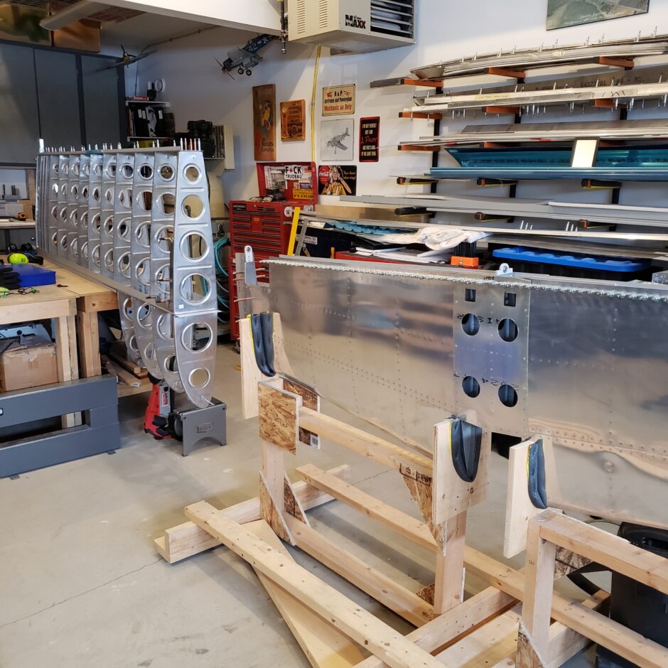
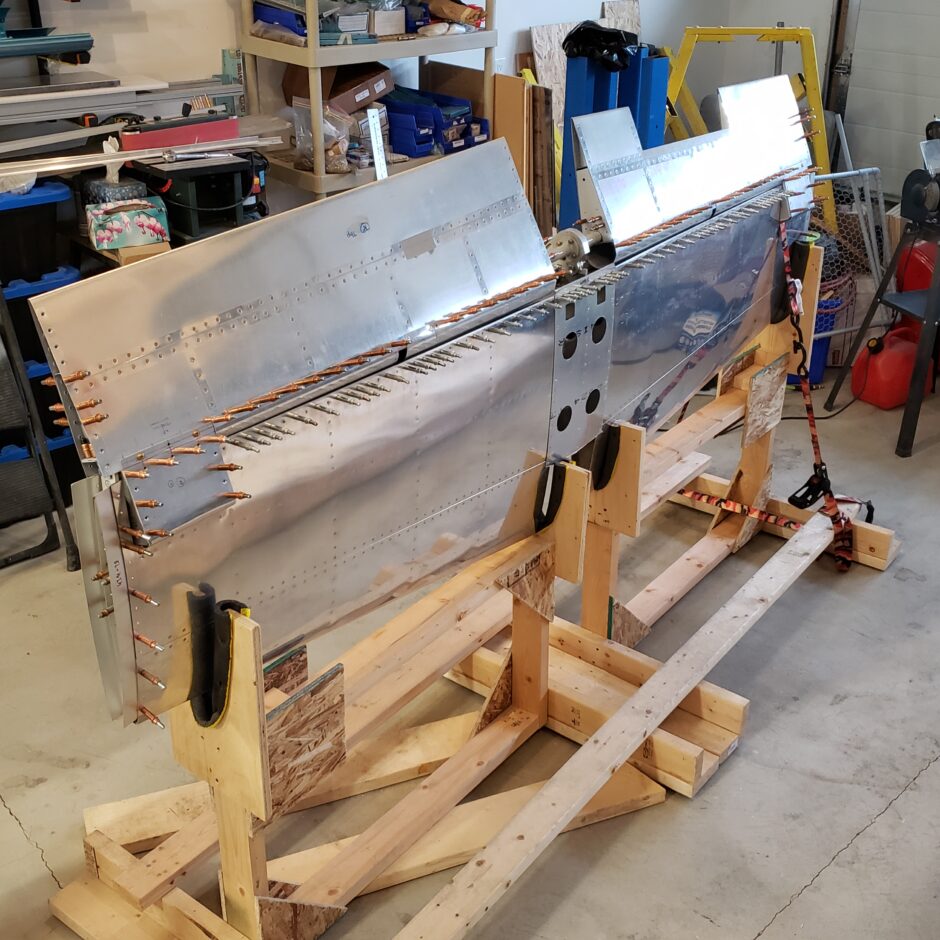
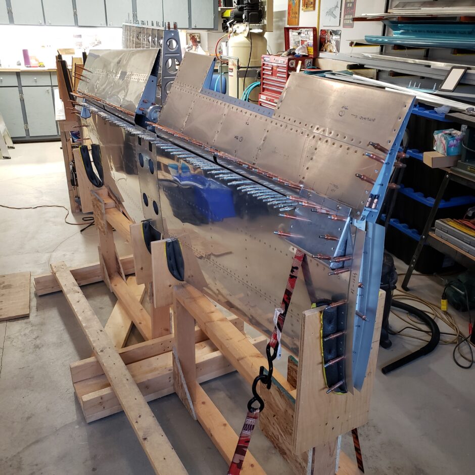
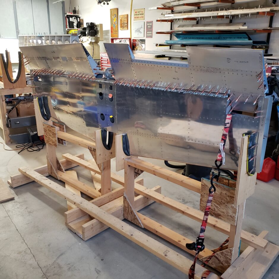
I’m glad I built the fixture to hold the horizontal stabilizer trailing edge up. I couldn’t imagine trying to do all this filing with the stab laying flat on the bench.
You might also wonder why am I filing? I asked that question too. I did attempt to use a sanding disc on the angle die grinder, and while this took off the material quicker, it didn’t save any time as I had to spend more time straightening out the line. In the end, it ended up being quicker to just file (while using the appropriate file) and eyeball up a straight line. Focus on the high points, and keep filing.
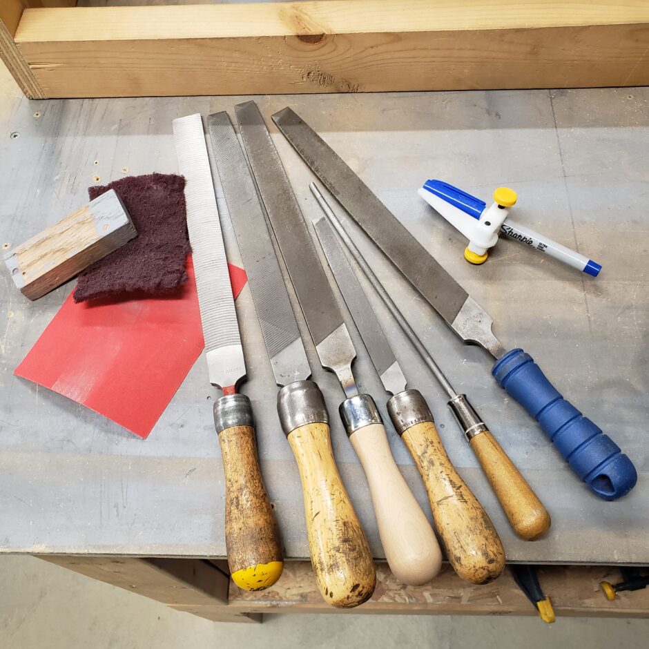
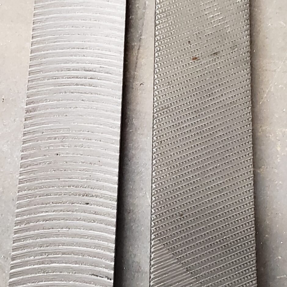
Speaking of appropriate files, these are the ones I used on this job. From left to right: Vixen file; Aluminum Type A; Bastard Cut; Fine Cut; small diameter round file (this is actually a chainsaw file and it works really well); Flat Second-cut file.
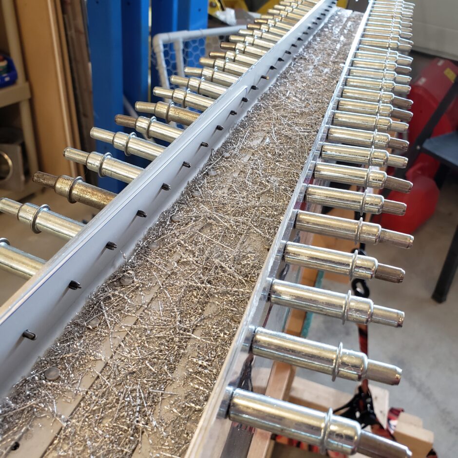
In the coming pictures is a really close shot of the Vixen and Aluminum Type-A files. The Vixen file was used for 90% of the material removal. This thing is like using a hand plane on wood. It just shaves off the aluminum. It took me a bit to get the technique down, but once I did, I could really remove a lot of material in a fairly quick amount of time. The trick is to use some pretty heavy pressure. After an 20-30 minutes of this you’ll definitely need a break.
In the picture below, you can see the how the Vixen file shaves off the aluminum in little twisted strands, not just in little filings.
The Aluminum Type-A also takes off a lot of material quickly. I found it worked better in areas near corners were I couldn’t get the Vixen file to work as well. This file is quite a bit more coarse than is the Bastard cut.
After doing the rough work with these I would then work my way down through the Bastard file, to the 2nd Cut, then to the Fine cut file to produce a really smooth edge. As the finished product neared completion, I also progressed into several fine sandpapers to get a really nice, smooth and polished finish.
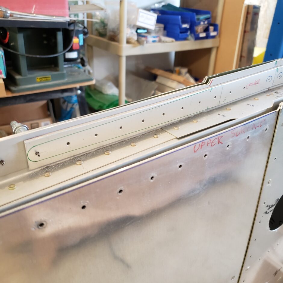
As I continued to file down, I started to come up on the doublers on the upper and lower surface of the horizontal stabilizer. As you can see in the picture below, I started to taper these to remove some of the excess material and to also create clearance for the elevator leading edges.
You can also see that the inboard side is getting filed down much more than the outboard edges. As the elevators and horizontal stabilizer are tapered, this meant that the inboard side had to have much more material removed vs the outboard side.
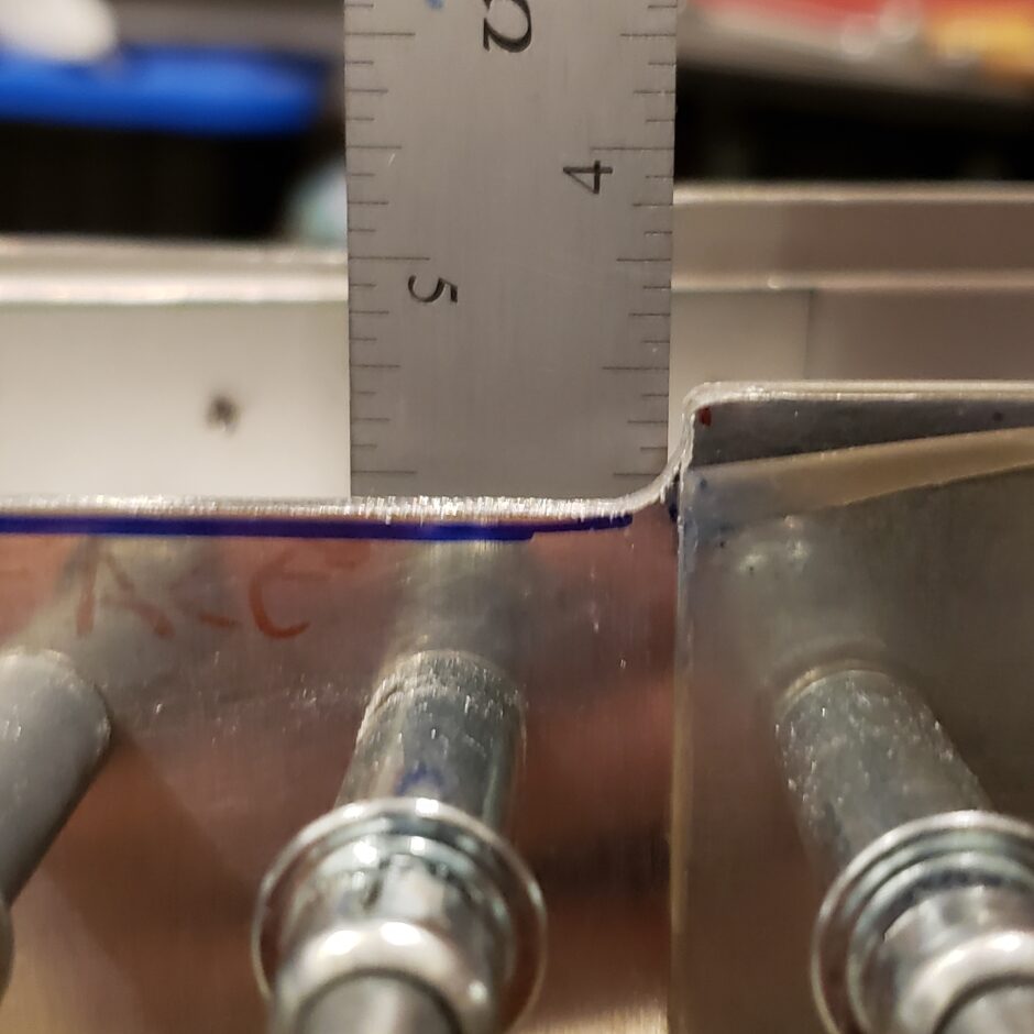
Just to put things into perspective, here’s a quick measurement as I was filing.
Here are some details on how I filed down the doublers.
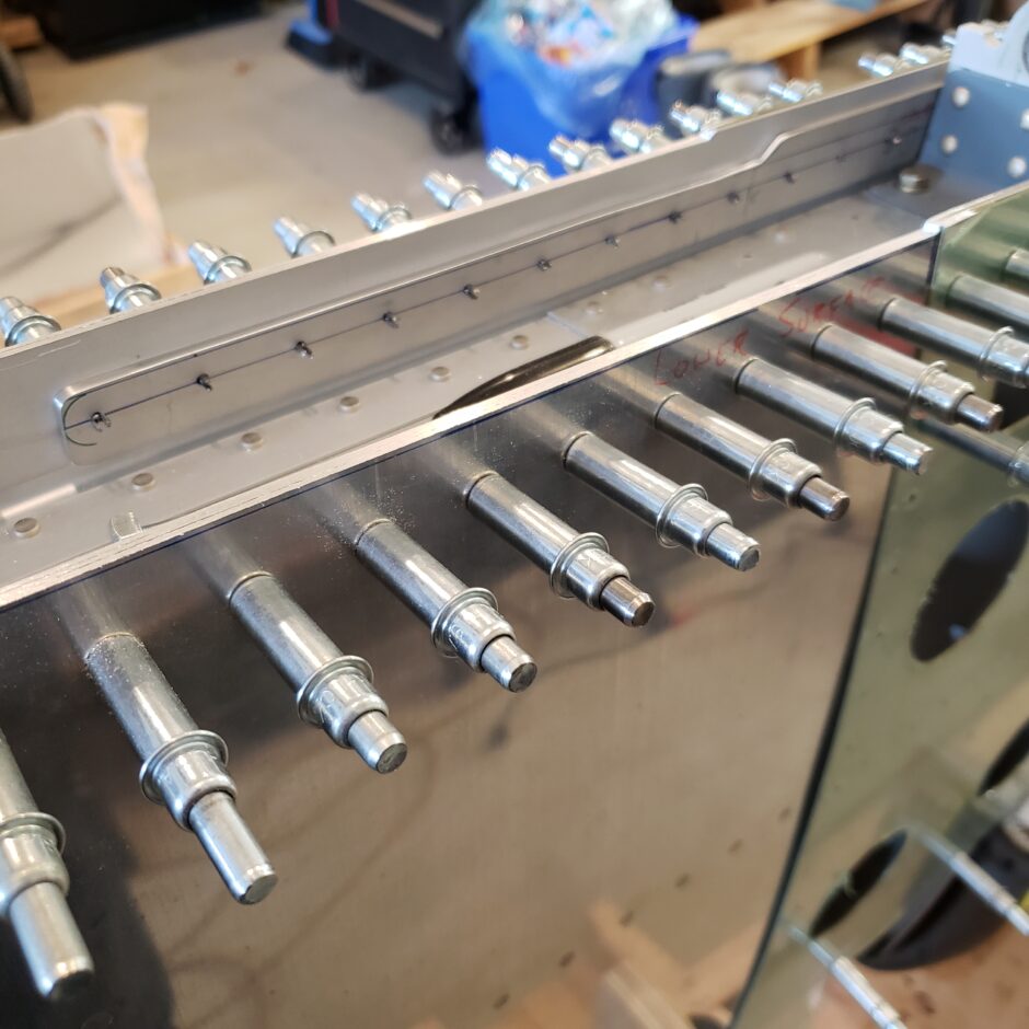
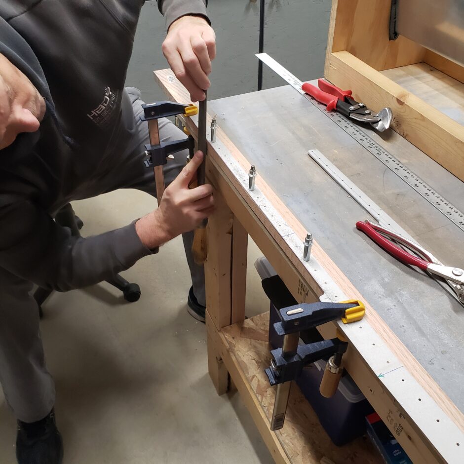
In the next few pictures you can see Garet and myself working to get straight edges in these doublers. The key here is that we used a piece of oak as our guide when filing. Set the layout line (or cut line) along the edge of the oak. As the oak is hardwood, you can file right up to it and really not take off any of the oak. This worked really well in achieving the straight edges in the doublers.
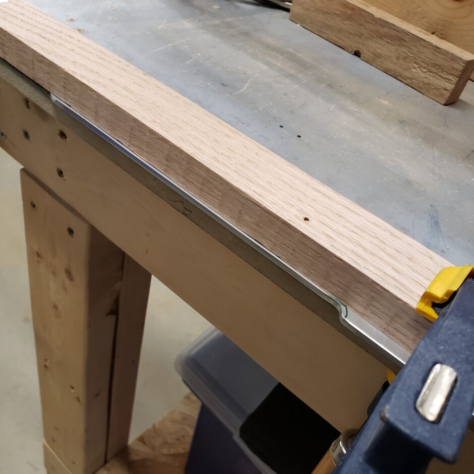
Here is one of the methods that I used to mark the cut line with the straight edge.
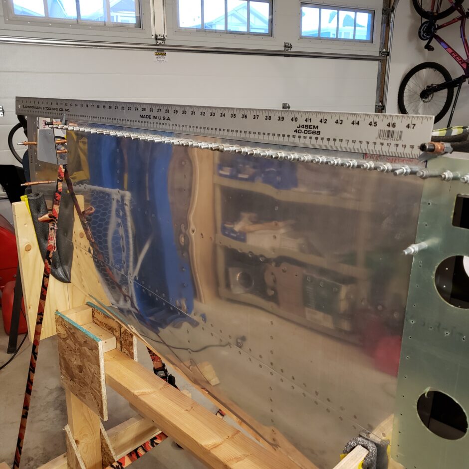
Finally I was able to get the elevators mounted. However, even though they were mounted didn’t mean I could get full up and down travel. This was something that surprised me. It didn’t occur to me that as the elevators would rotate, the leading edge would increase in thickness as well. It took quilt a bit of additional filing at the inboard edges to continue to make clearance for the leading edge. This really wasn’t an issue out near the tips.
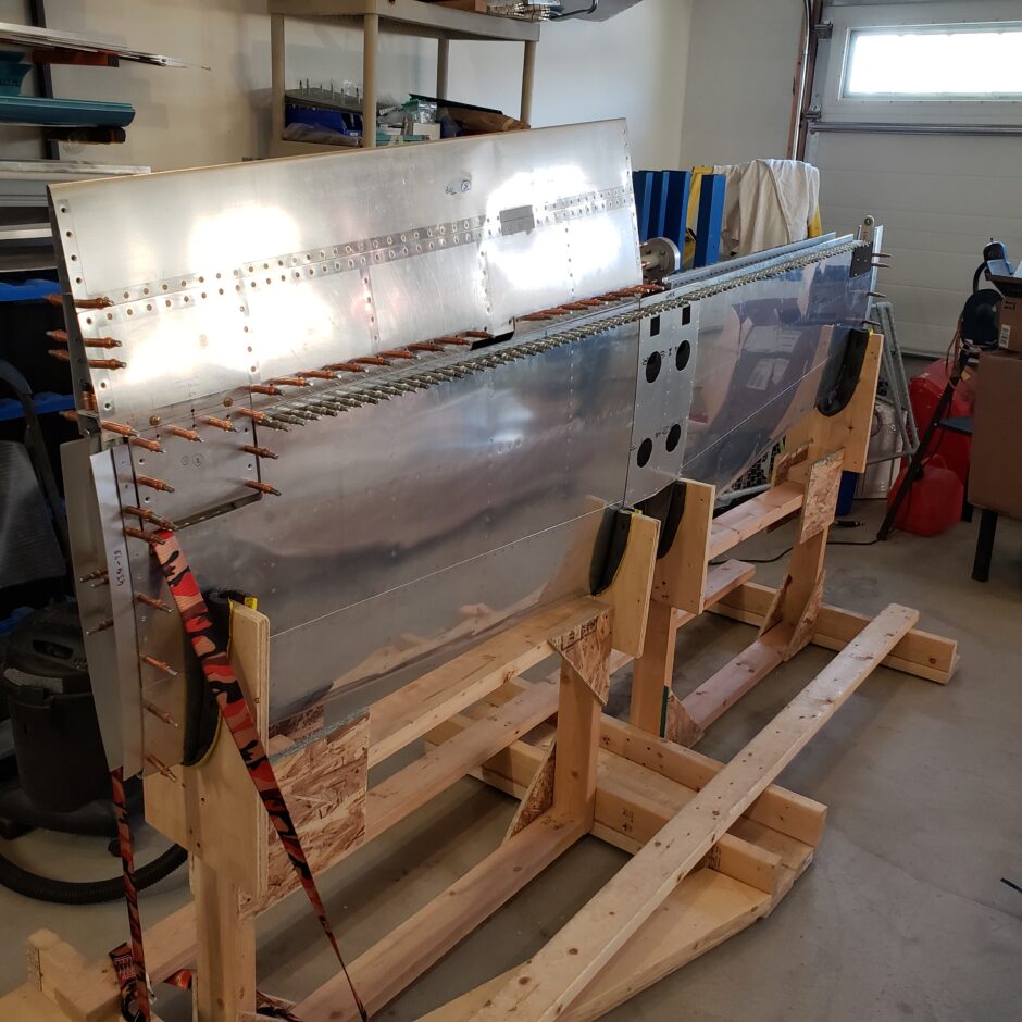
In the picture below you can just see how the gap at the root end of the elevator is slightly thicker. I just kept filing and taking little by little off the high spots where the leading edge of the elevator would interfere with the horizontal stabilizer. I did this until I could get full travel up and down.
Here is a close up picture of the bellcrank and elevator stops on the hinge bracket. The next pictures will demonstrate the travel.
Here is the full up travel.
Here’s the down travel.
With full travel achieved, it was time to put the elevators together then to mount them on the stabilizer. I bet you wouldn’t be surprised to find out that this too changed things just enough that I had to do just a bit more filing to make it perfect. Like I said, this whole process was A LOT of work, but all in all it’s a beautiful thing to see it all come together.
Please comment. I love to hear from my readers. Thanks again for coming along for this ride, you make my work worthwhile.
Leave a Reply