Today I’m ready for a change of pace on the elevators and I’m going to start building up the balance weights. I’ve been putting this off for a while as I know it’s going to be a complicated event. However, like everything in building planes, the process becomes clear when you chunk it down and tackle it in bite sized pieces.
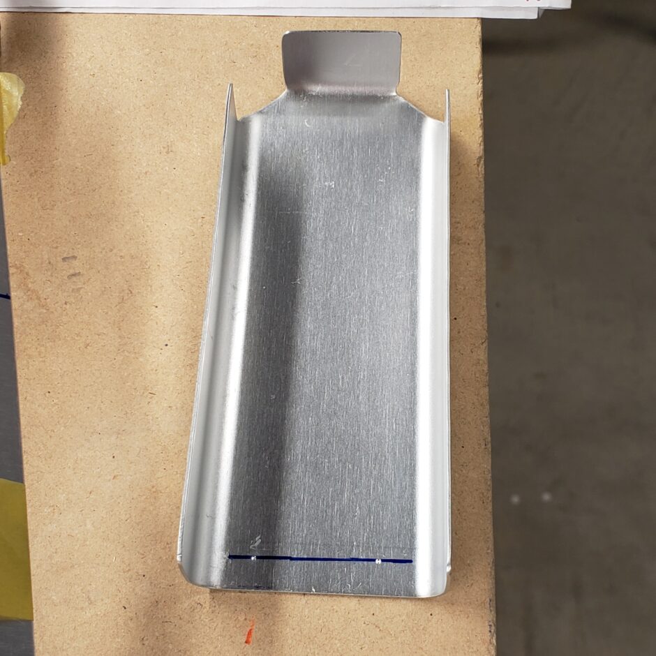
To begin, I needed to do some additional forming of the balance weight skins. The radius of these needed to be tightened up quite a bit from what the people at HPA did in the Czech Rep at the factory. I accomplished this by working the skins around some clamped pieces of wood that had an appropriate radius. I worked it by hand pressure and a few light taps with the rubber mallet.
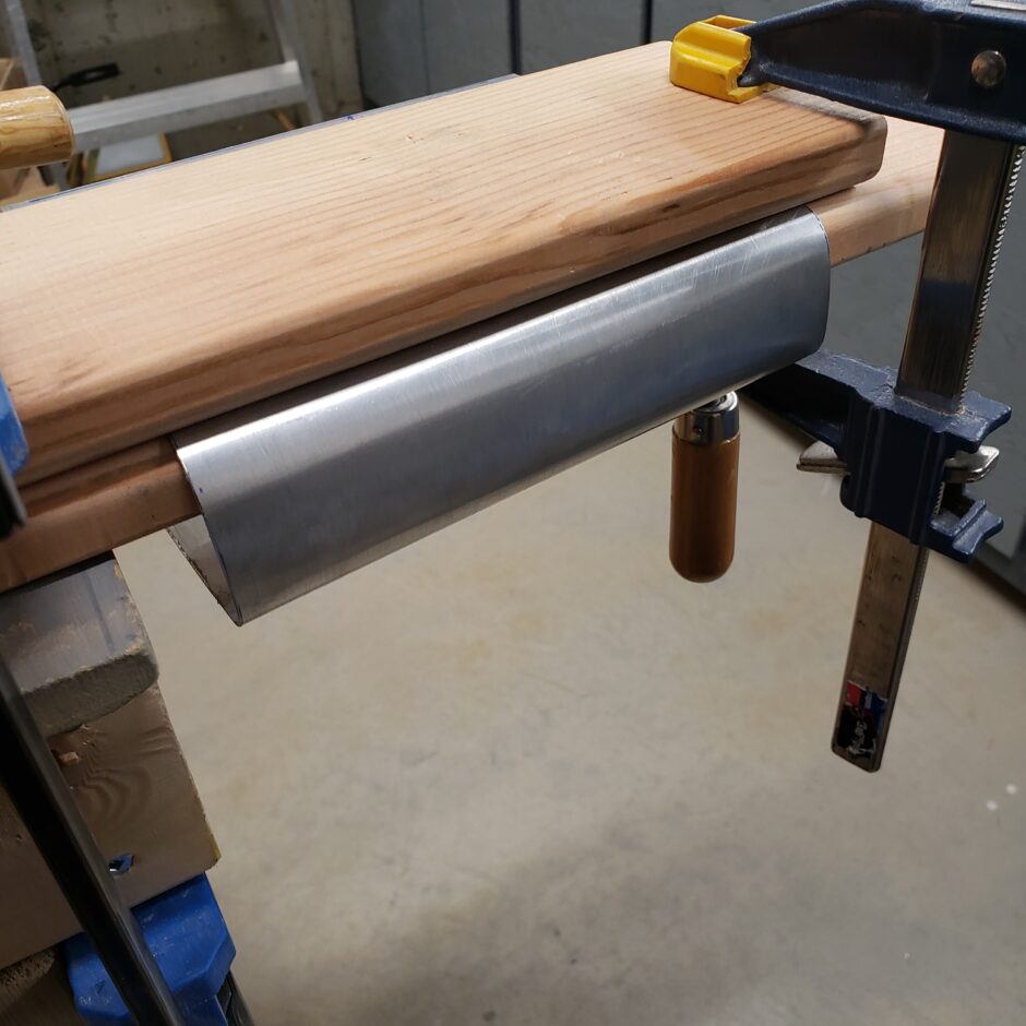
Shown below is the skin wrapped around the balance weight end rib. What makes this a bit challenging is that the balance horn tapers, so the inboard side is thicker than is the outboard side. Here on the inboard side, there is a flat area on the forward side of the rib. There are 2 rivets that get located here to hold that front side of the skin in tightly to the rib…but, the corners have to be rounded. This results in the front of the skin wanting to bow out. It’s a real catch 22 until you can get the radius of the bends sufficiently formed. Oh the fun!

Below is the outboard end. It’s slightly narrower, where the front of the rib on this end will only have one rivet holding the skin to the rib.
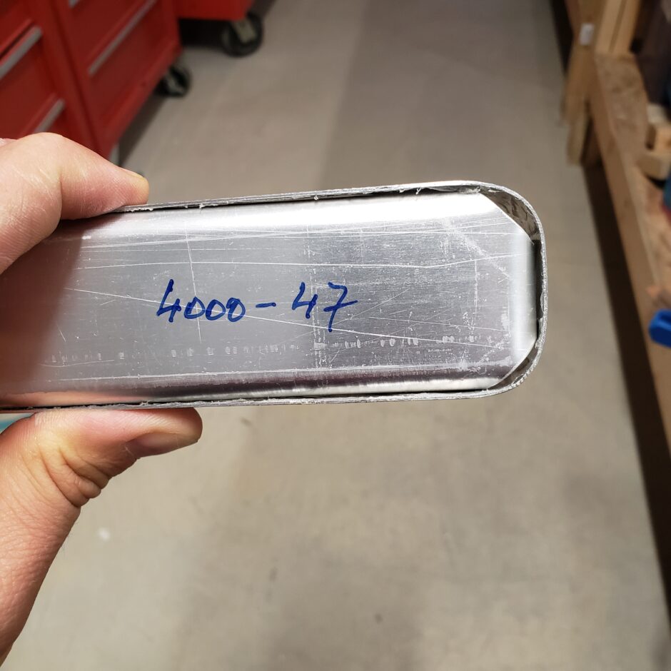
As the forming continues, with a clamp and a couple cleco clamps, I’m able to get the skin to fit as it should around the rib.
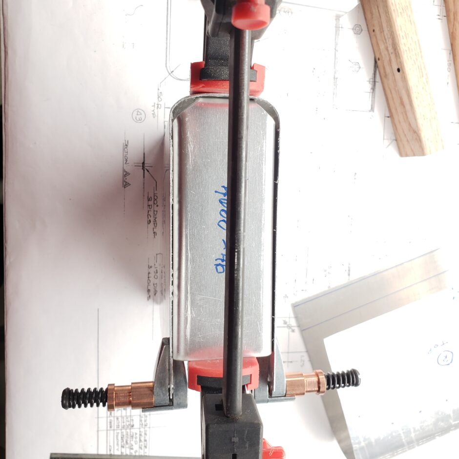
Here is a shot of the inboard end. Also starting to fit quite nicely.
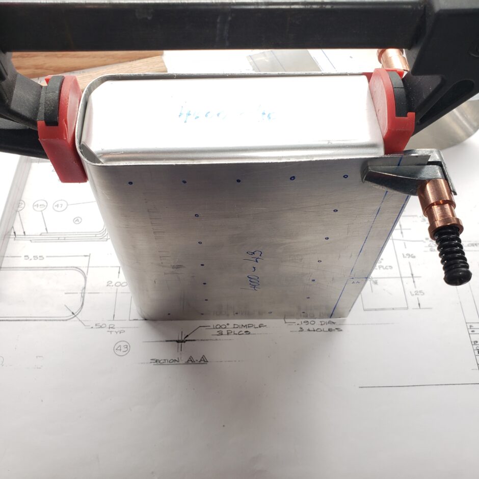
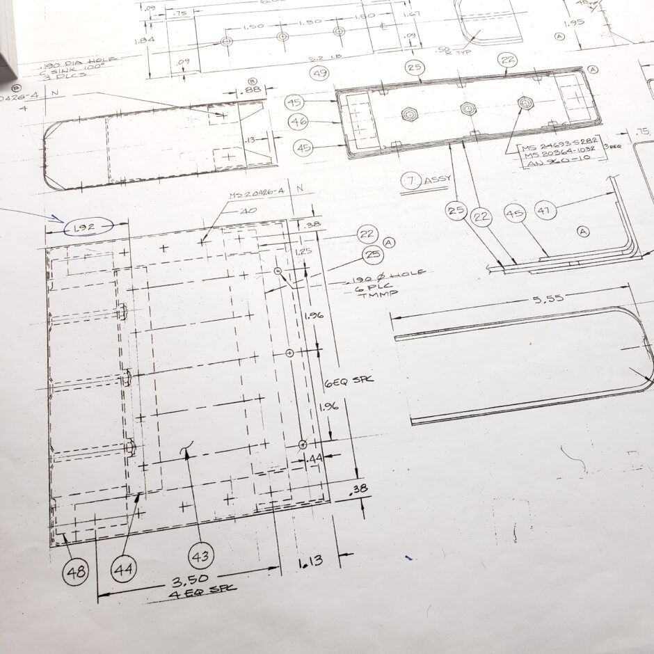
In the picture below, you can see what the plans are like for the build up of these balance weights. There is no assembly instruction (step-by-step) on how to assemble. Again, this is where you take it one piece at a time.
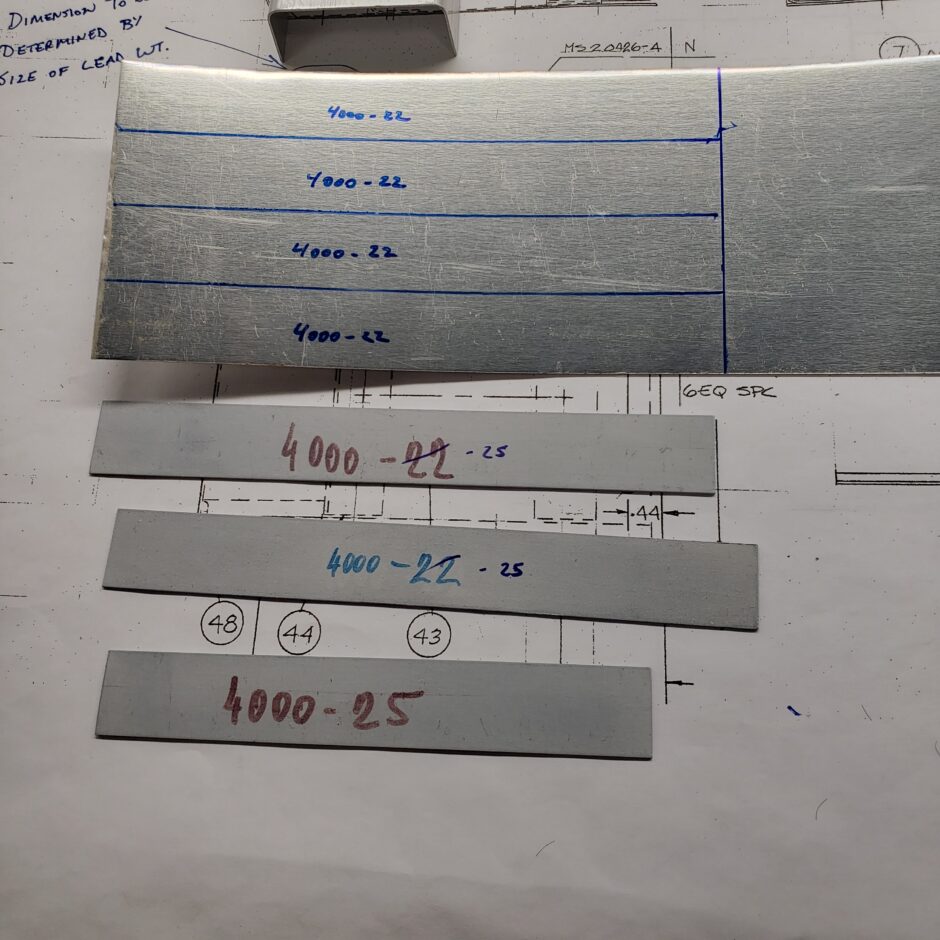
My next observation is about some spacer strips (#22 and #25 in the drawing). What I’m finding is that the parts supplied with the kit are not cut to the correct size…or identified properly.
In this picture you can see that the #25 parts are shorter and the #22 are longer. I’m opting to cut down the kit supplied #22 to make them into #25 strips. And I can easily cut out some new #22 strips from some scrap aluminum. Not a big deal, just another task deviation that takes time.
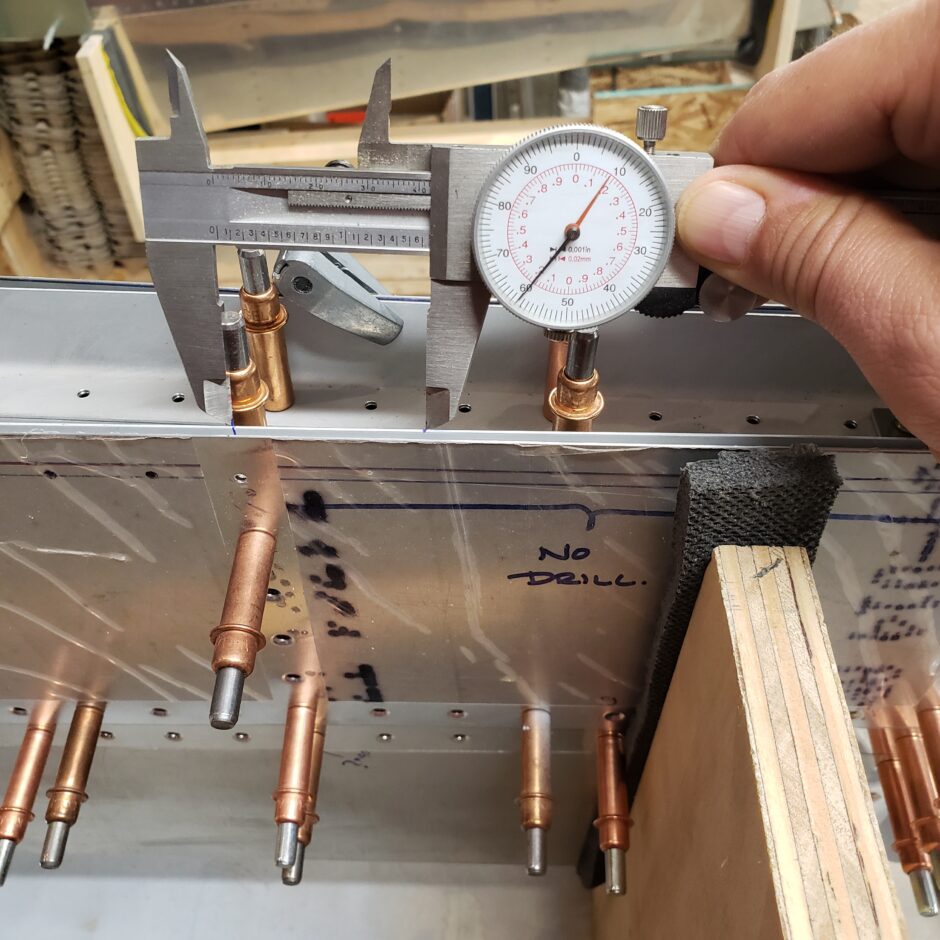
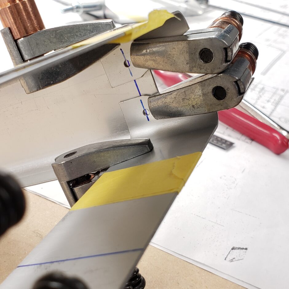
Moving back to the elevator, here I’m doing some layout for the fasteners that attach the balance weight to the elevator. The balance weight is affixed by 3 structural screws (top and bottom). In the picture below, I’m just identifying the spacing.
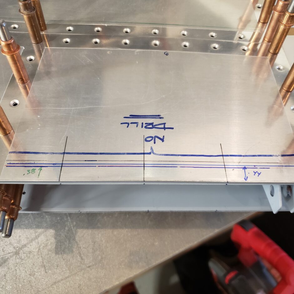
The picture below is an extension of the photo above where I’m working out the layout for the fasteners. As there are several layers overlapped, I need to know by how much the layers overlap, as well as keeping appropriate edge distance. There are a few different lines drawn here but I’m getting it figured out. I don’t think I’m confident enough now to drill it all, so I’m going to move back to building up the balance weight assemblies.
In the picture below, I’m using some painters tape to help me hold all these parts together. I definitely could use the help of one of my plane building buddies to help me with some extra hands.
I also have tape holding the #22 and #25 spacer strips on to upper and lower supports that build up the aft end of the balance weight that attaches to the elevator. It’s hard to describe how these pieces fit in, but you’ll see in the coming pictures how it all comes together.
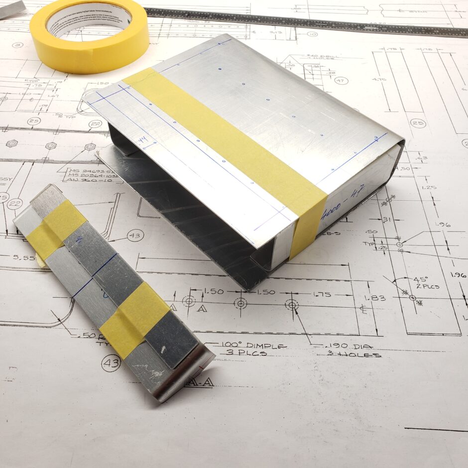
Shown here are the 3 pieces of the upper support. The lower part is the same.
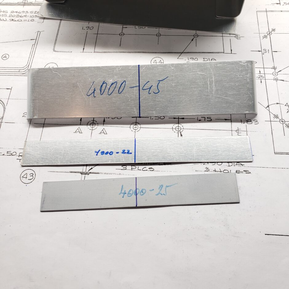
Shown below, you can see how this stiffener assembly fits in against the side ribs. Note why the one spacer is shorter than the other. It’s there to act as a filler strip to make up the thickness of the end ribs.
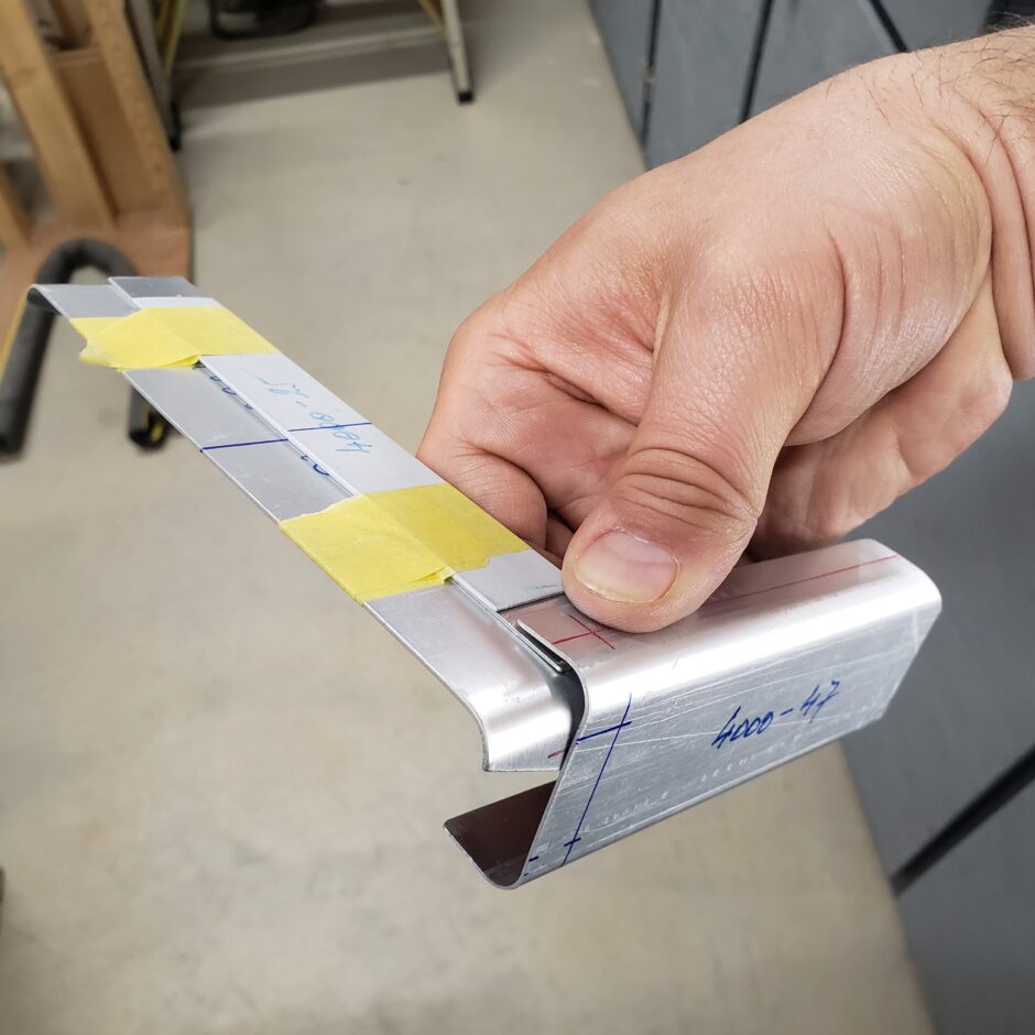
These next few pictures you can see how it all starts coming together and why an extra set of hands would be so helpful in juggling this little assembly. Thank goodness again for the cleco clamps!
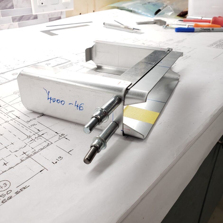
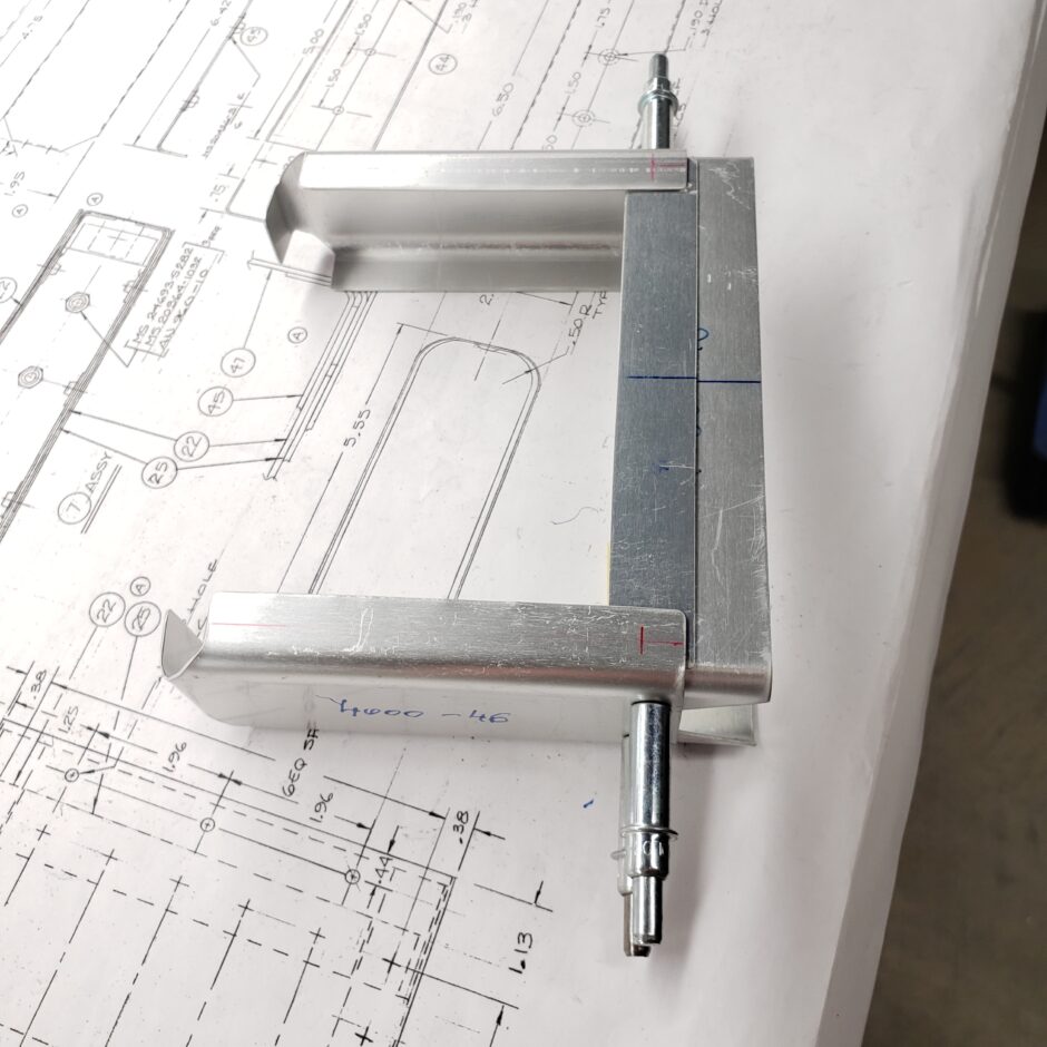
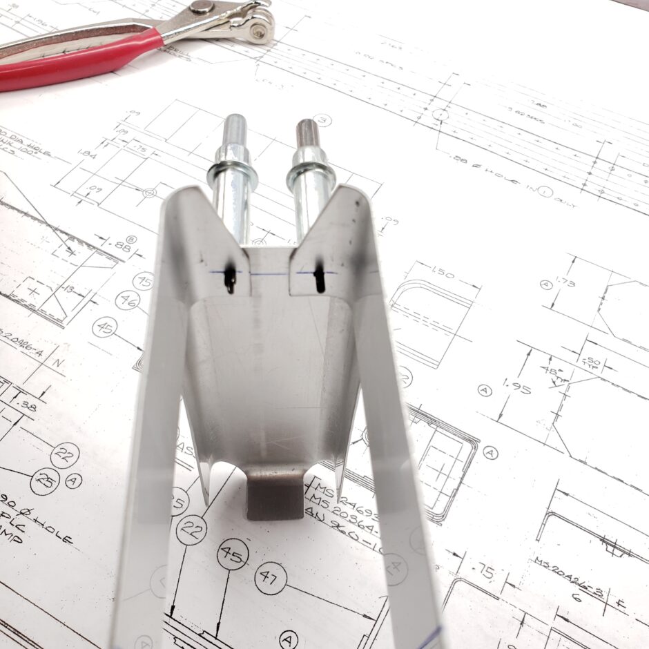
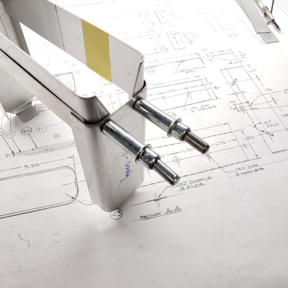
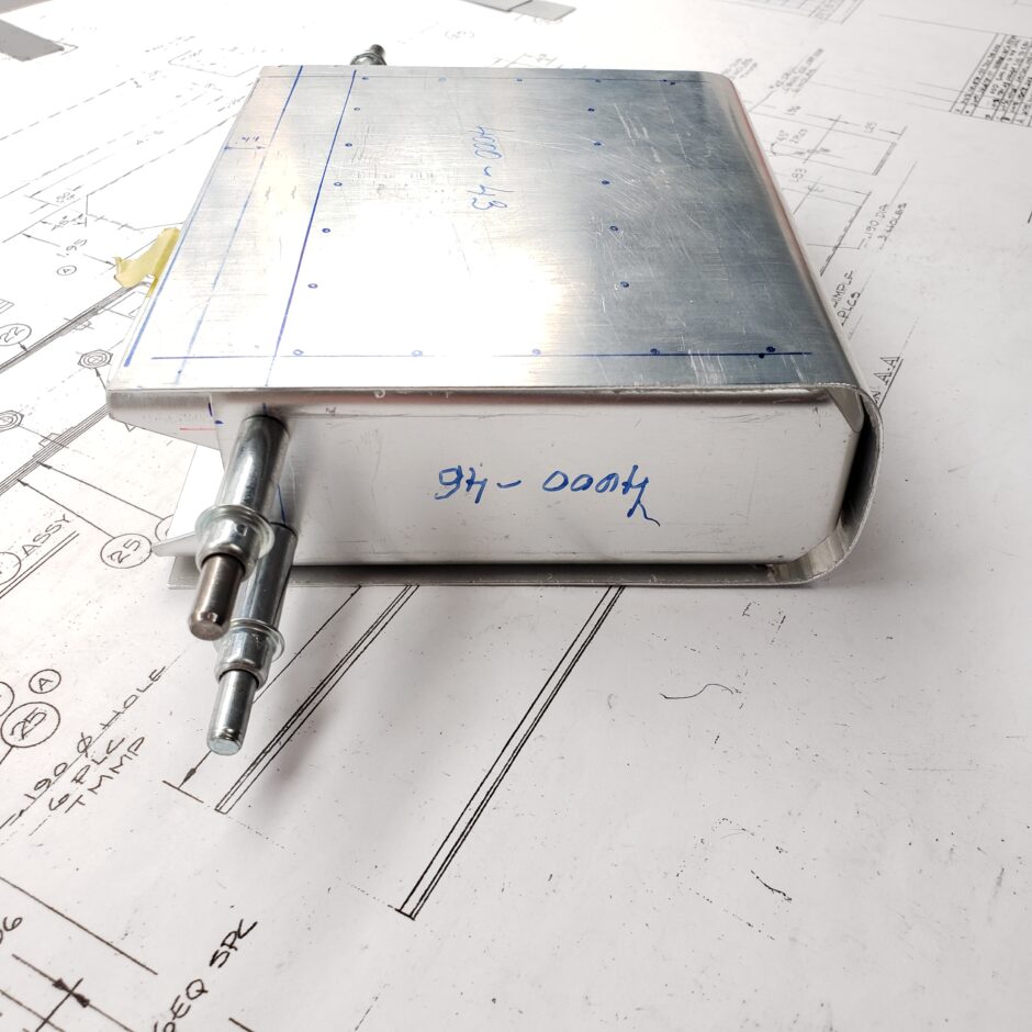
The way I began to assemble these assemblies was first by drilling marking and drilling the inner stiffeners. This seemed like the best place to begin as edge distance didn’t leave much choice as to where the placement of the rivet hole would be.
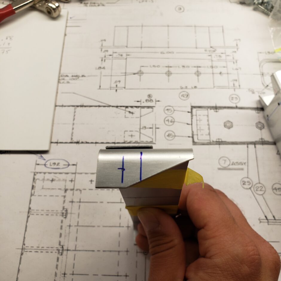
Next was to mark the dimension of where the upper and lower stiffeners need to be located. This is the line that the rivets need to align with on the side ribs.
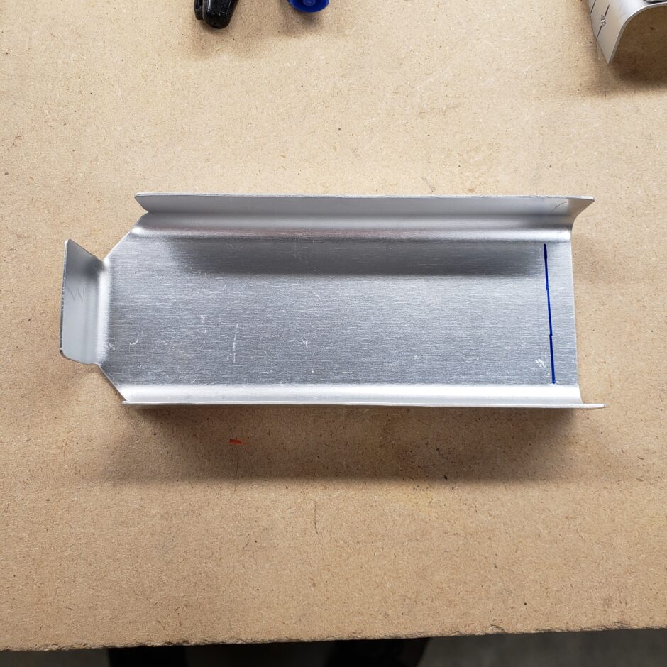
Then I clamped all the parts in place and the holes previously drilled in the upper and lower stiffeners now align with the rivet line I drew on the inside of the end ribs.
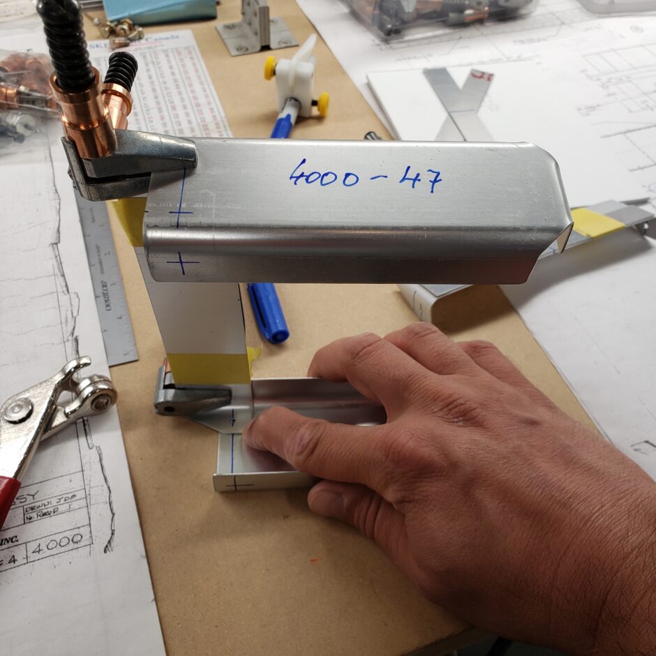
Here is the assembly all clamped together. One more final check before drilling.
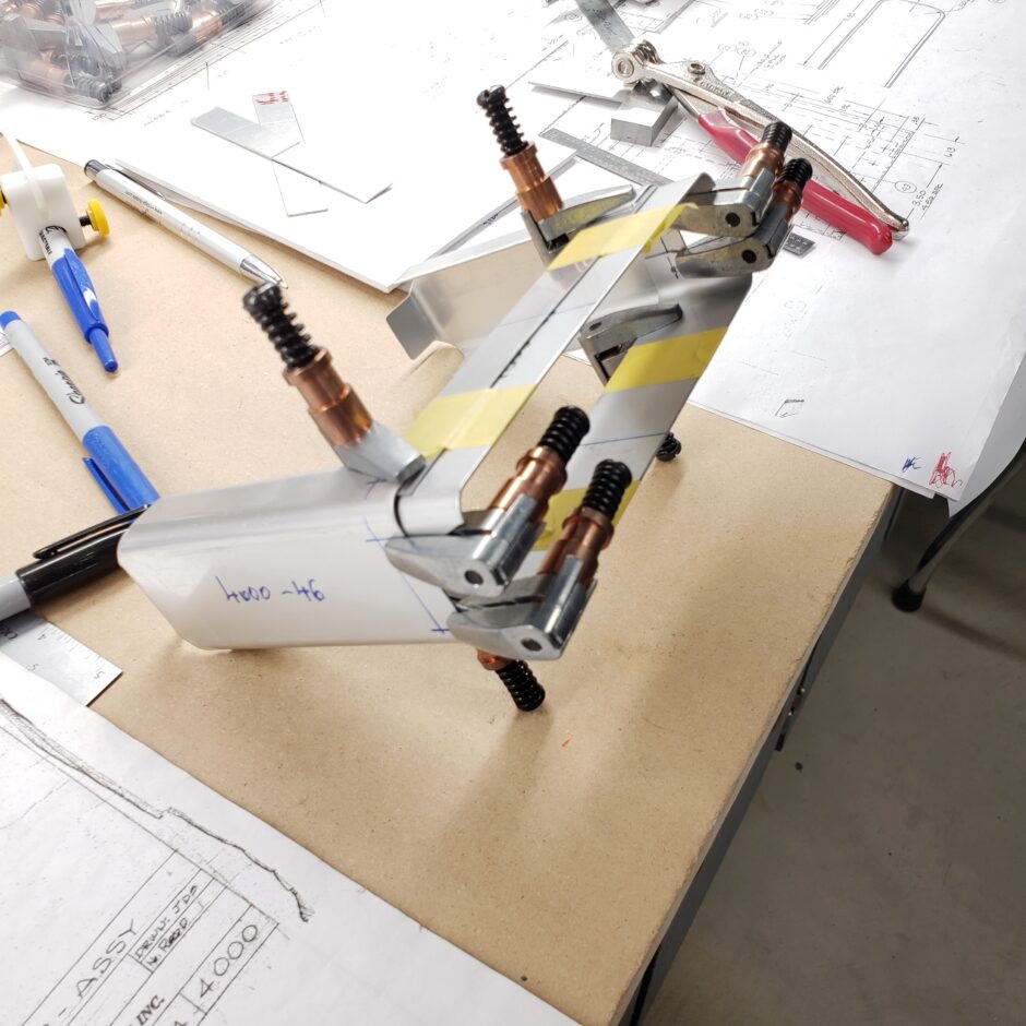
When drilling these parts, I didn’t just want to drill the hole as it’s hard to get the drill squarely set. So I used a long drill bit to just start the location of the hole. As you can see below,
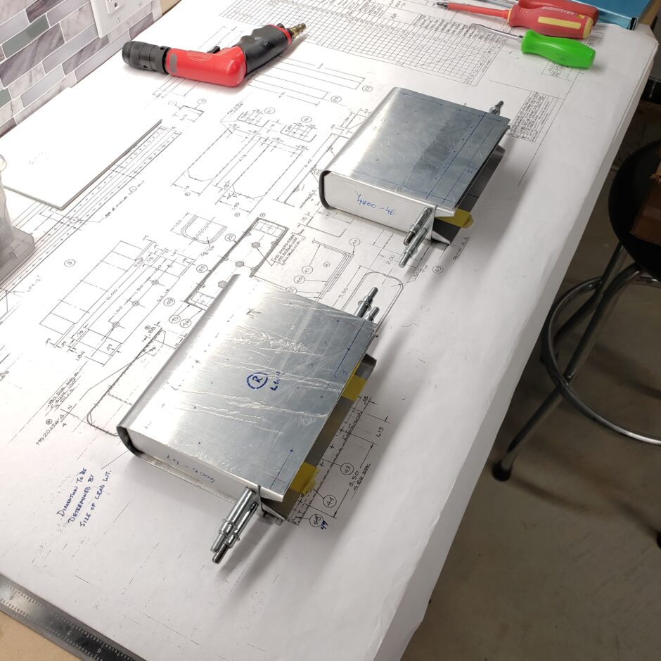
The balance weight structure is slowly starting to take shape.
The next step was to drill the rivet holes at the forward end of the ribs to help pull the leading edge of the balance weight skin tightly against the rib. I chose to back drill these ribs from the aft side, as it was too difficult to accurately measure the hole locations from the forward side.
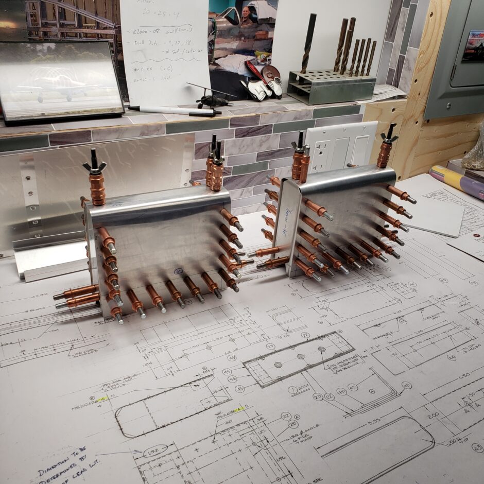
Once the ribs were drilled, I found using the wingnut clecos worked really well here to help pull the front of the skin in tightly to the ribs. The way the skin is bent, the leading edge side wants to slightly bow out.
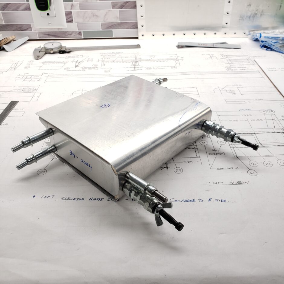
Moving along I drilled out the rivet holes for joining the ribs to the skin.
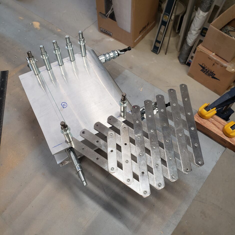
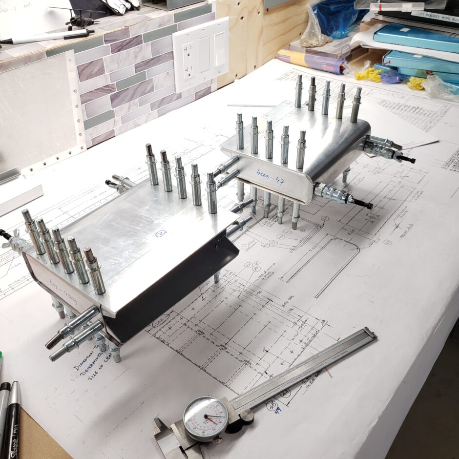
I’m now going to progress with building up the interior structure of the assembly. This structure forms a slot where the balance weight can slide over the elevator skin and spar. This structure also adds stiffness for the balance weight to be fastened with screws, which will clamp down on all these layers joining the elevator to the balance weight assembly.
In the picture below, I have one of the spacer strips held in place with some tape. Again, working alone, I just don’t have enough hands.
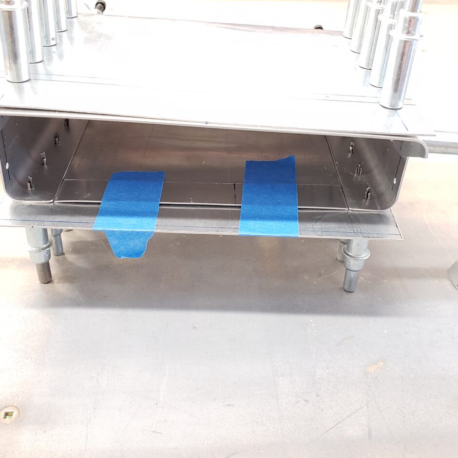
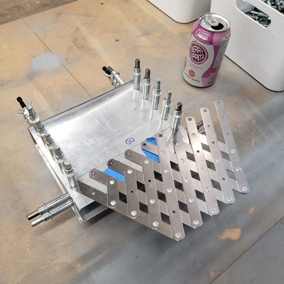
With all the layers of the rear stiffener taped or clecoed in place, I was able to use the rivet fan to evenly space the required number of rivet holes.
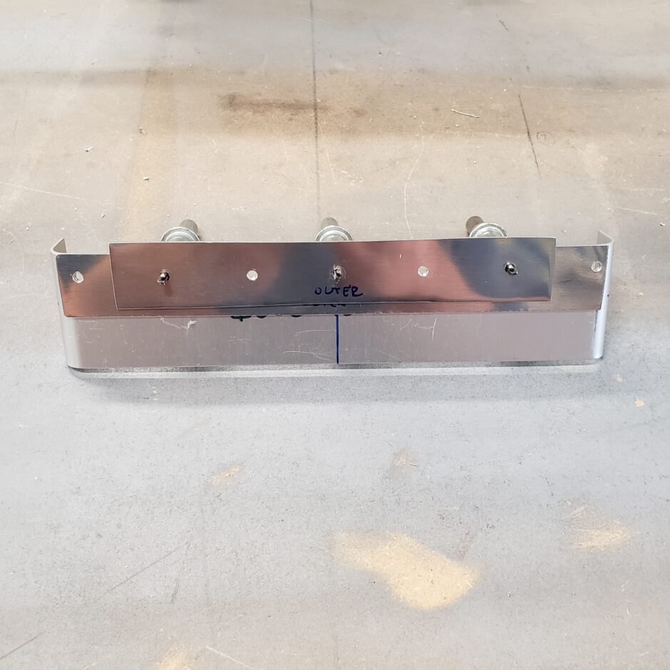
In the picture below, you can see the build up of the spacers. You will notice that I offset the smaller spacer to provide a bit more edge distance.
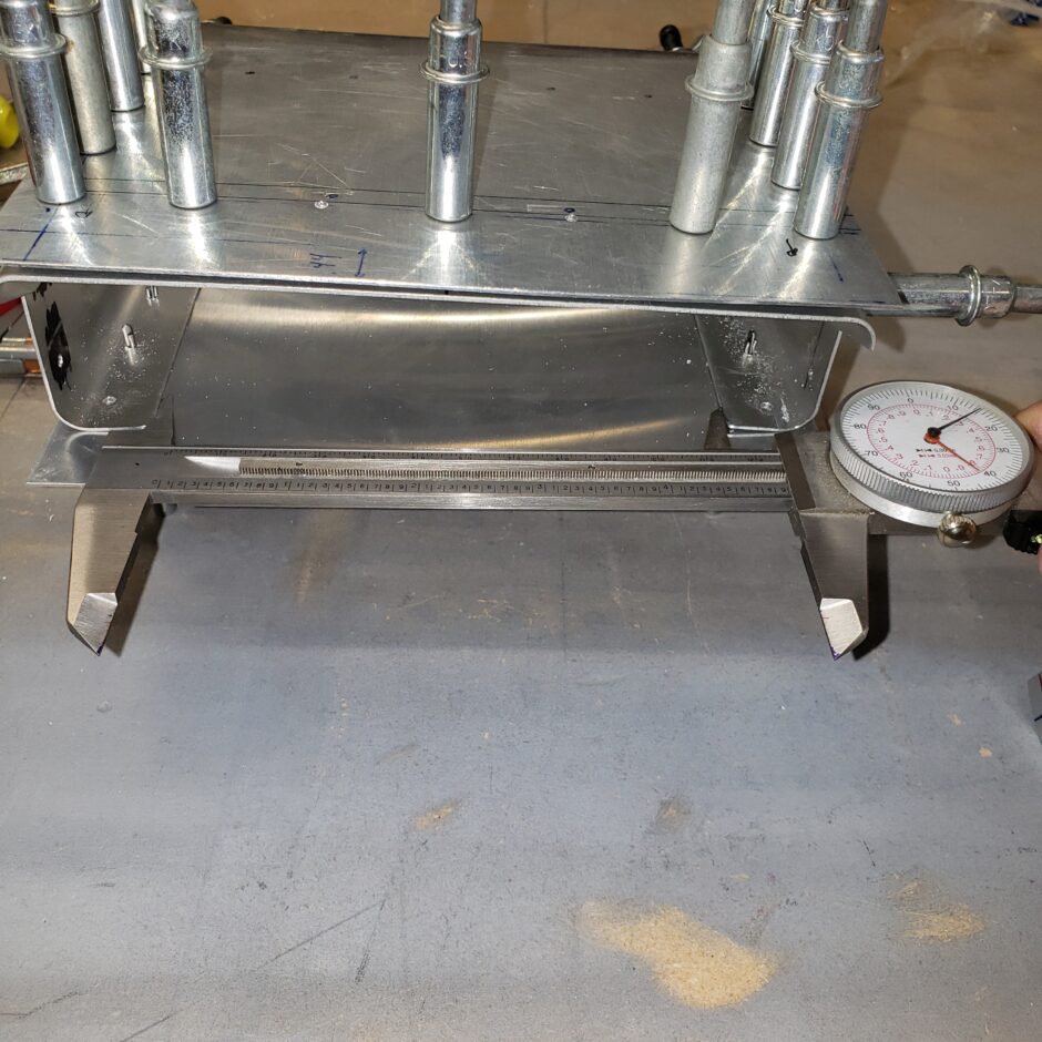
Working on the other side. Here I’m using the caliper to accurately measure the length of the spacer material.
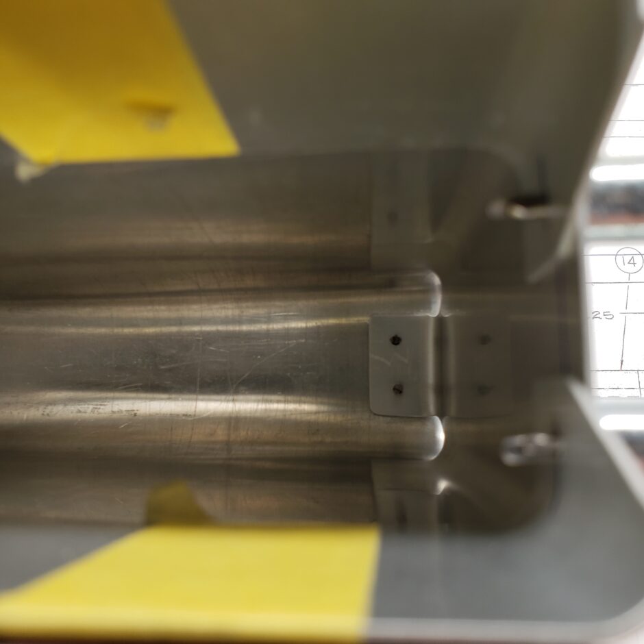
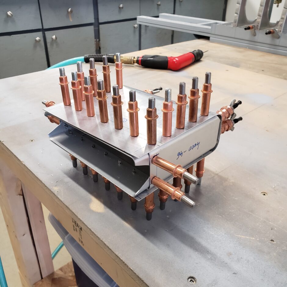
In the pictures below, I have the balance weight assemblies final drilled to #30 and here you can see the slot where the balance weight slides over the elevator skins. This slot area will eventually get drilled with 3 holes per side to attach the assembly to the elevator.
Please comment. I love to hear from my readers. Thanks again for coming along for this ride, you make my work worthwhile.
Leave a Reply