As the right elevator is starting to come together, today I started by looking at some of the remaining parts to begin planning ahead, in particular, the leading edges and balance weight assembly.
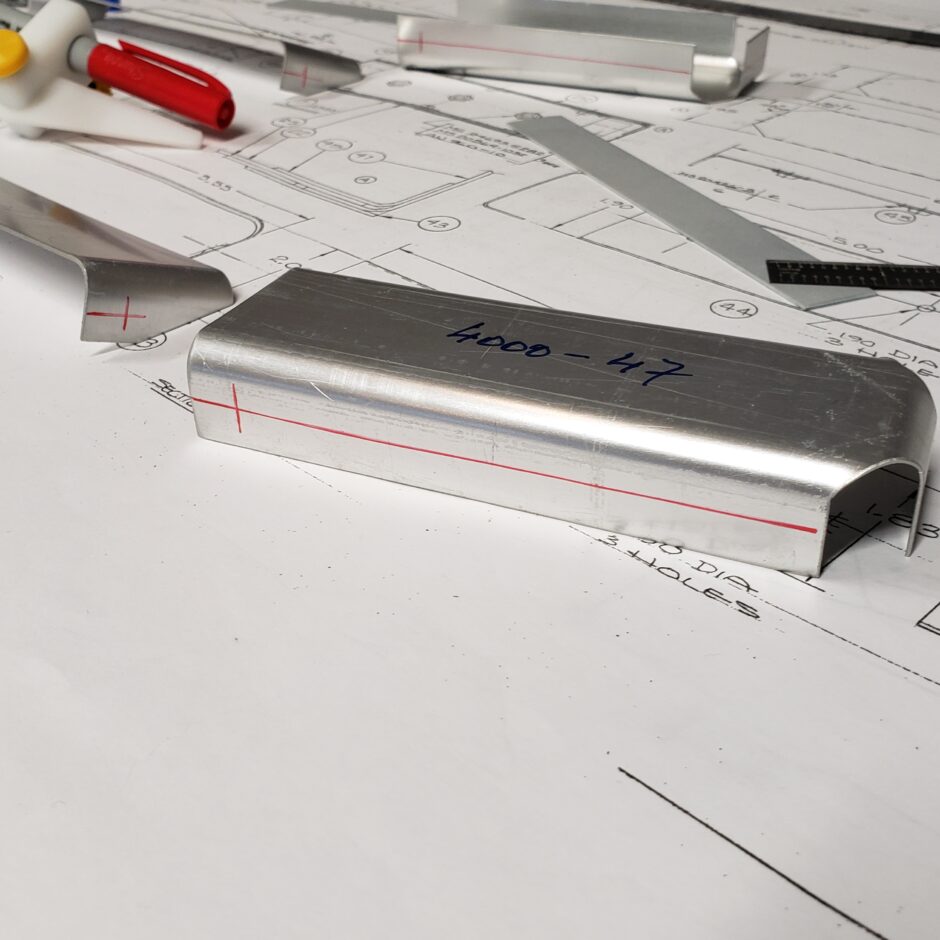
The leading edge skins needed to be trimmed to length, so I started with the layout. This was a bit tricky as I needed to mark around the preformed radius.
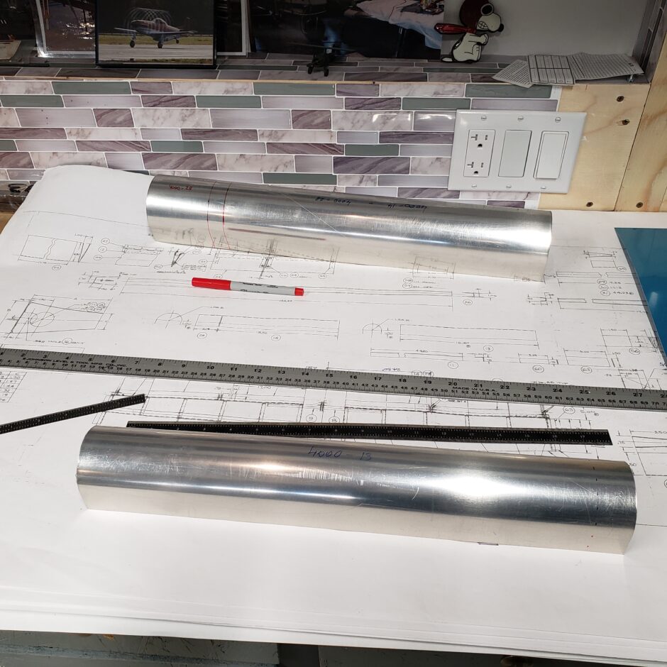
I started the layout with making some dash marks along the required dimension.
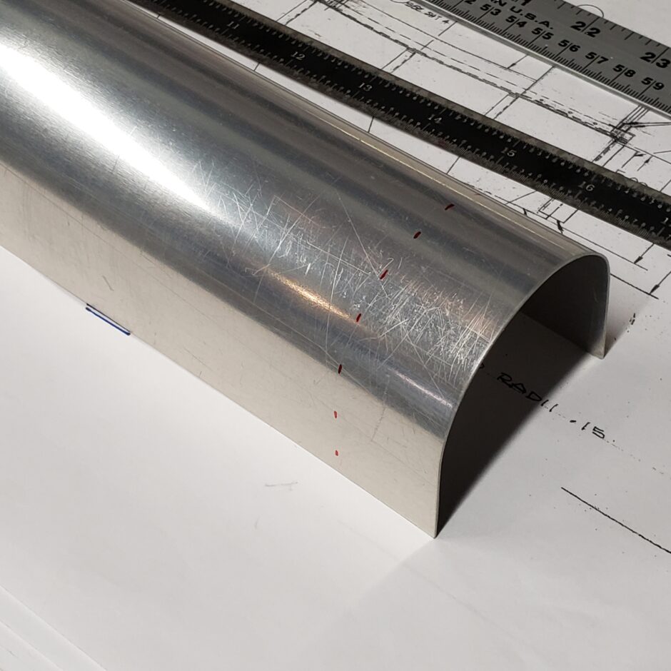
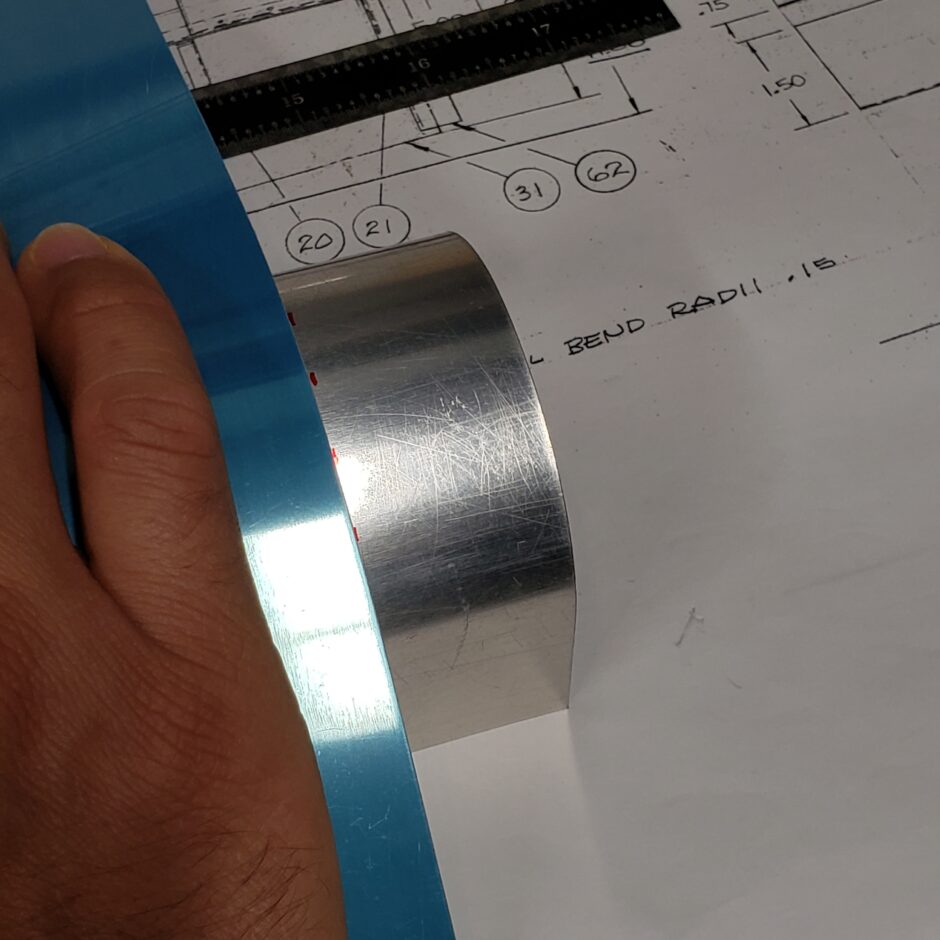
Then I found a thin piece of scrap aluminum that I could use to wrap around the leading edge to draw my cut line.
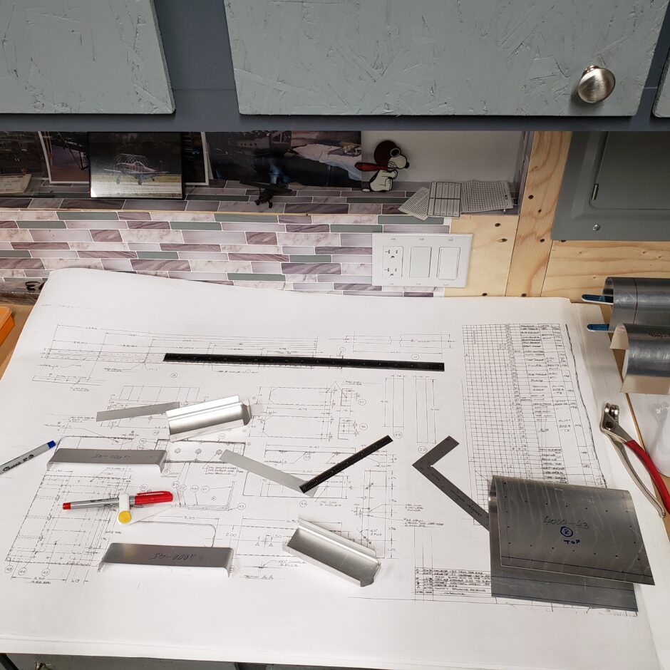
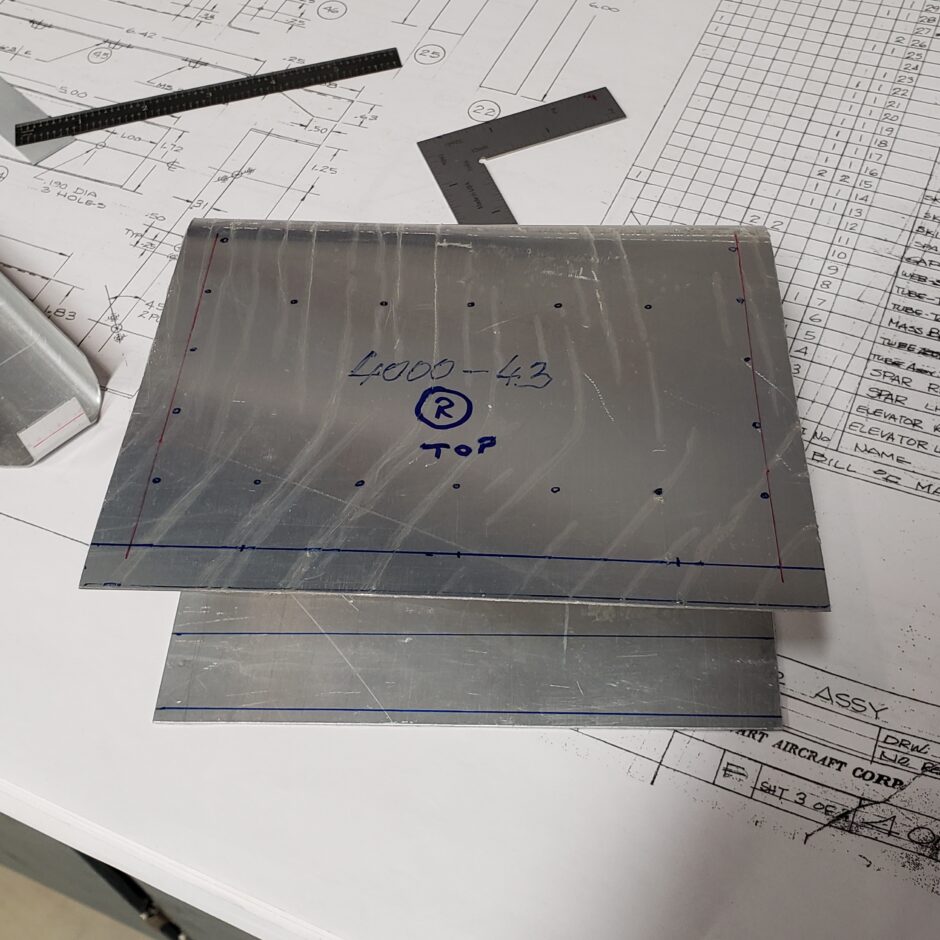
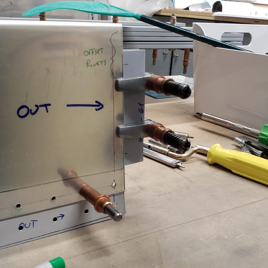
The image below, shows most of the parts needed to build the elevator balance weight assembly (less the lead weight).
I began with the basic edge distance measurements.
For the balance weight skin, I ended up having to not only mark the edge distance of the outside dimensions. I also added some measurement lines on the inside surface to help me judge the overall size of the skin and to help me determine if I needed to do any trimming. The dots on the outer surface were placed there by the folks at HPAI (from past experience, I don’t trust any of their rivet layout markings!).
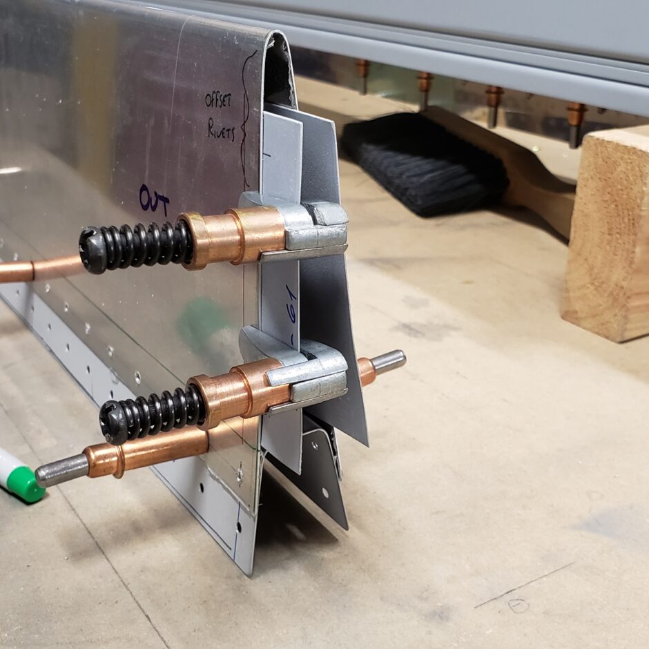
After playing around and attempting to test fit the elevator balance weight assembly parts, I’ve decided that I need to leave this task until I have a helper. These parts didn’t fit nicely together and will need some slight massaging to get a nice tight fit. I’ll need some extra hands when I do that. So for now, I’m leaving it and moving on.
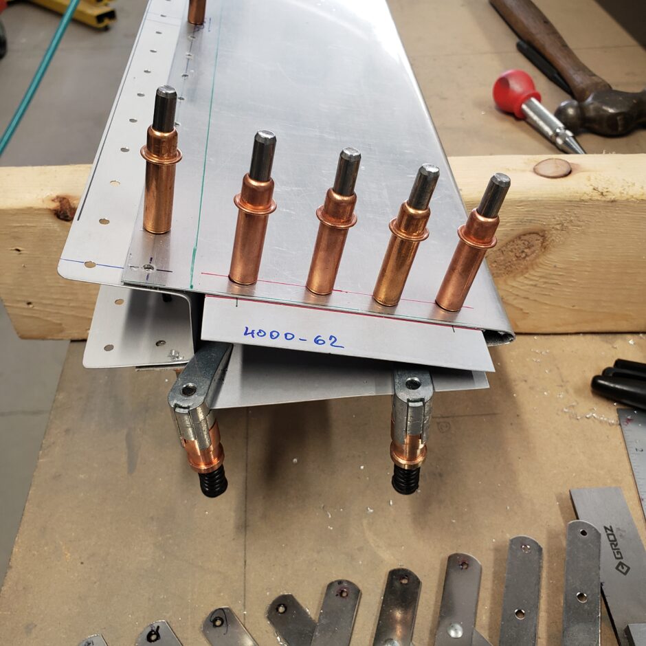
Drilling the skins
All the skins had been pilot drilled to #40, so I started to do the final size drilling up to #30.
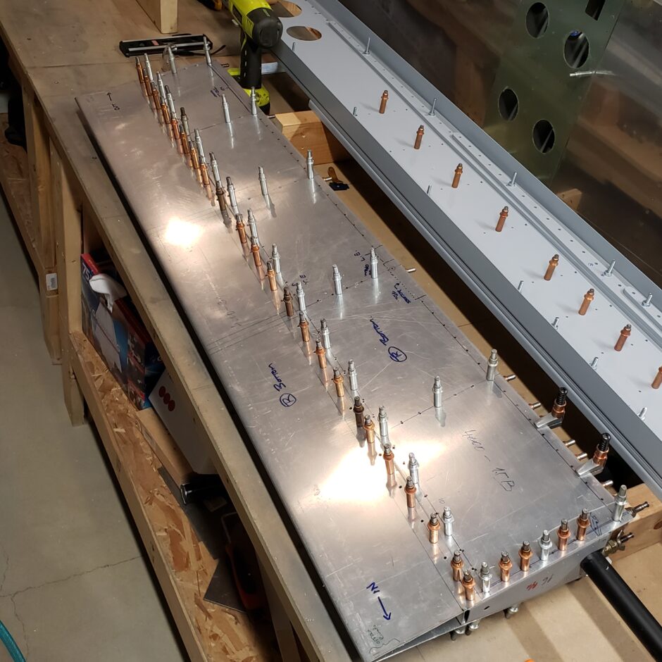
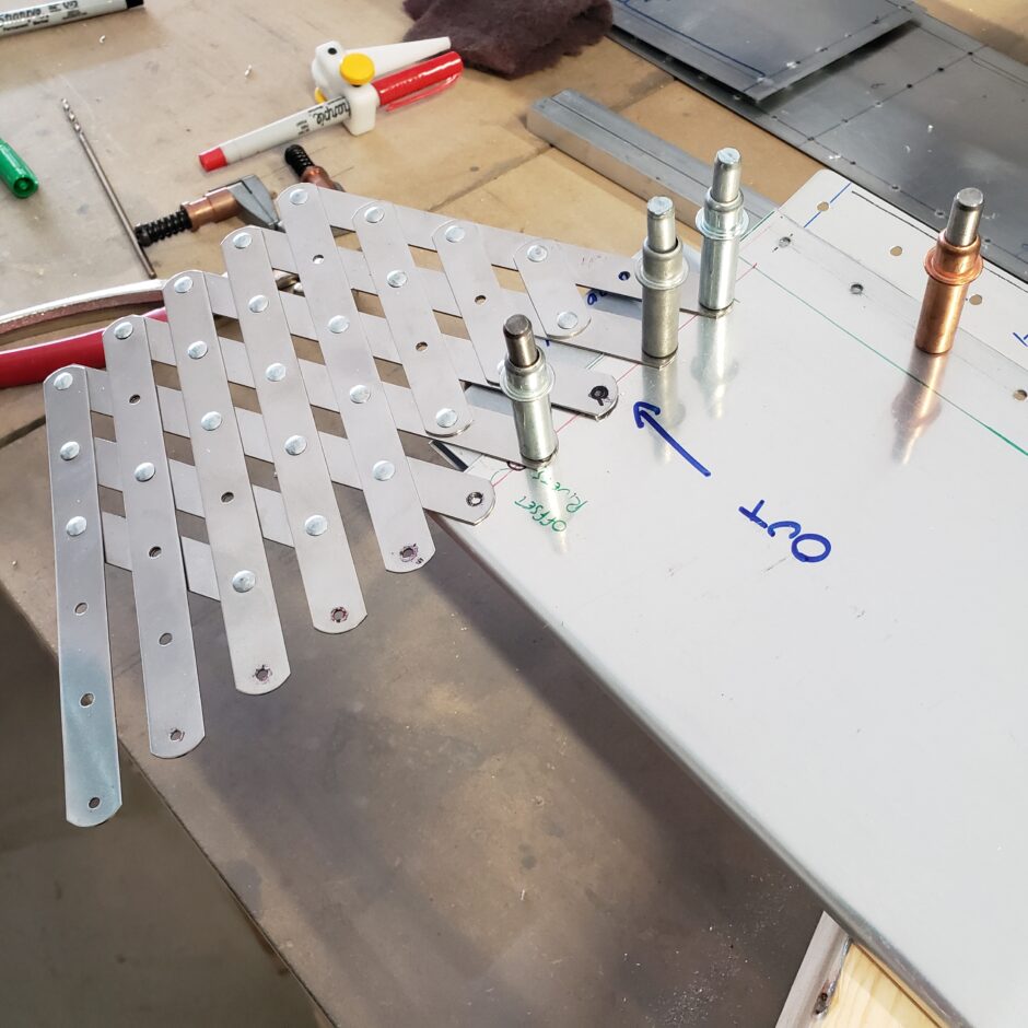
After the skins were drilled. I then tackled getting the end ribs in place that will close out the elevator. In the picture below, on the outboard side, the rib has a large flange which will also be used to fasten the elevator tip.
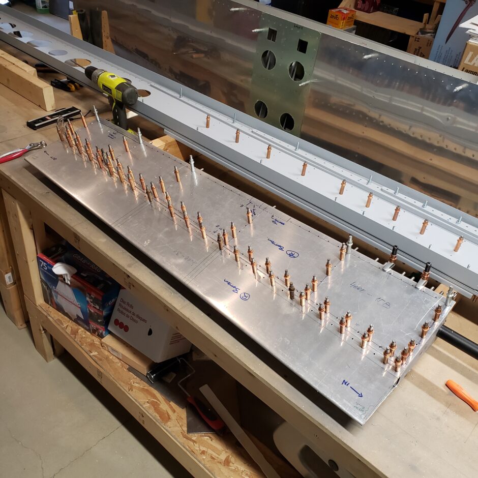
The layout for these end ribs is pretty straight forward with 4 rivets. I used the rivet spacer fan to evenly space the rivets. Pilot drilled and then upsized to #30.
The last job for today was to start dimpling the skins and elevator structure.
Please comment. I love to hear from my readers. Thanks again for coming along for this ride, you make my work worthwhile.
Leave a Reply