Today there isn’t much in the way of build progress, however I’m getting a little inspiration from a bit of visual progress. It’s really nice seeing the rudder coming together and I think you too will be excited to see some things that make the S-51 so cool.
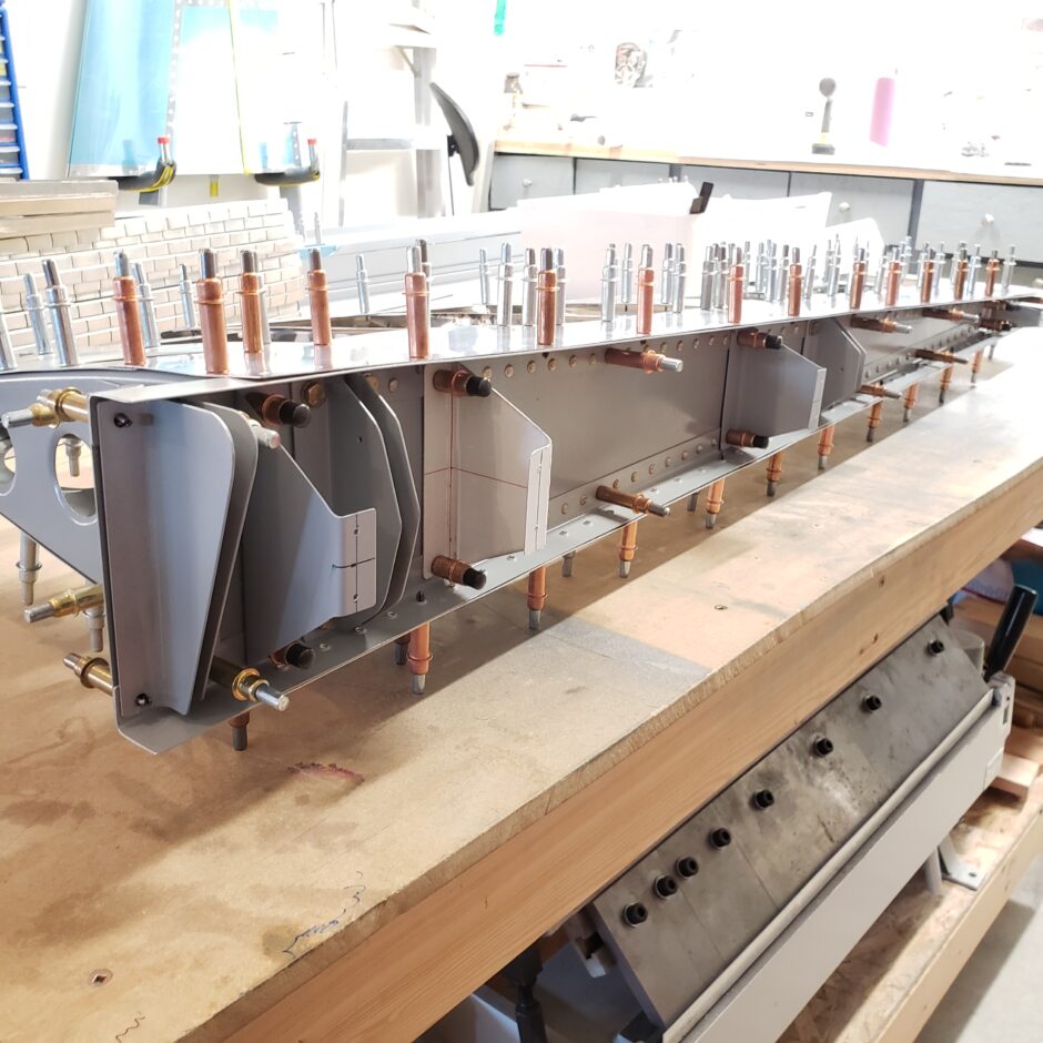
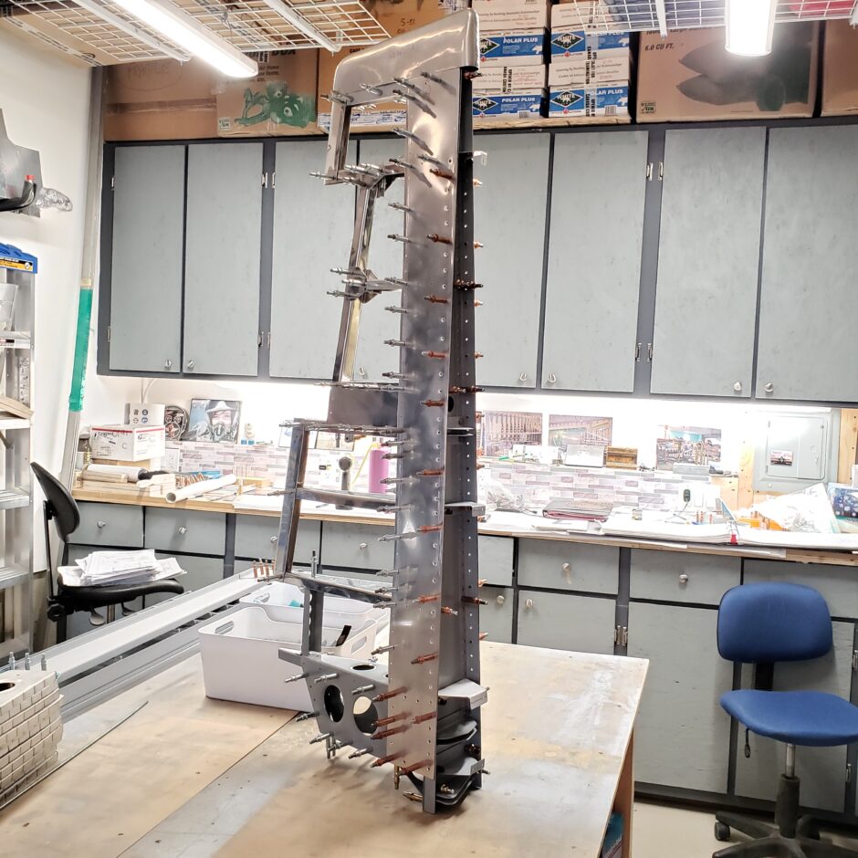
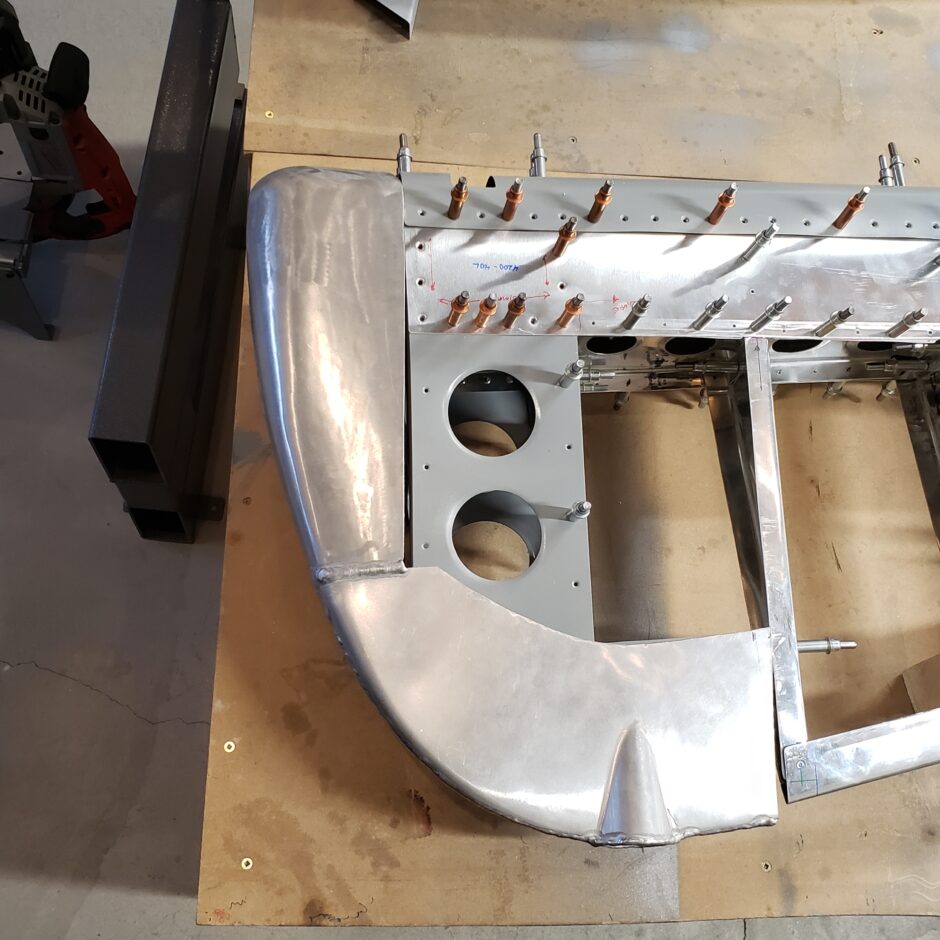
In the picture below, you can see all the cool stuff going on along the rudder spar. This is viewed from the lower side, the first set of brackets is where the rudder control pushrod will attach. Above that is a standoff to support the leading edge. Next is the lower hinge bracket, followed by another 2 standoffs, and then the middle hinge bracket. The other items at the upper end of the spar are not visible.
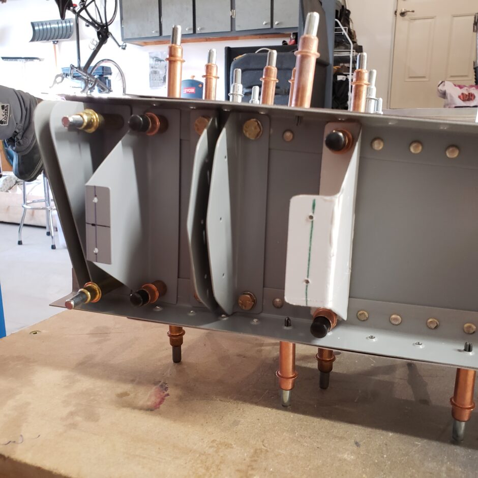
Here’s a different angle of the lower end of the rudder spar.
It’s pretty interesting that the rudder is actuated by a pushrod. I can’t think of any other homebuilt aircraft that have this design feature. Again, it’s one of the examples of the lengths that Jim Stewart has gone to to ensure that the S-51 is authentic to the big P-51. As the S-51 is a dual control aircraft, both the front and rear seats are equipped with rudder pedals. The front and rear seat pedals are connected by a pushrod. Then the rear pedals are connected to a bellcrank in the aft fuselage. The bellcrank then transfers the rudder inputs to a push-pull rod that actuates the rudder.
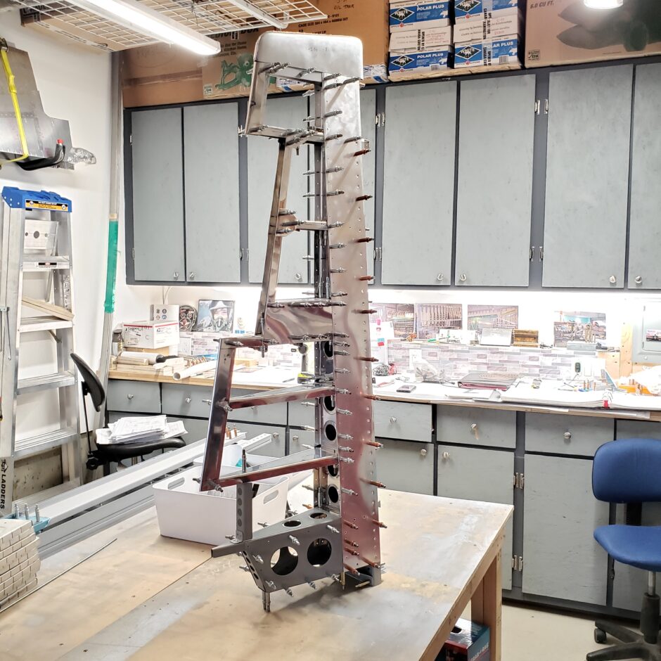
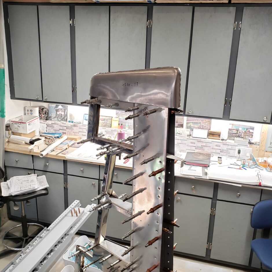
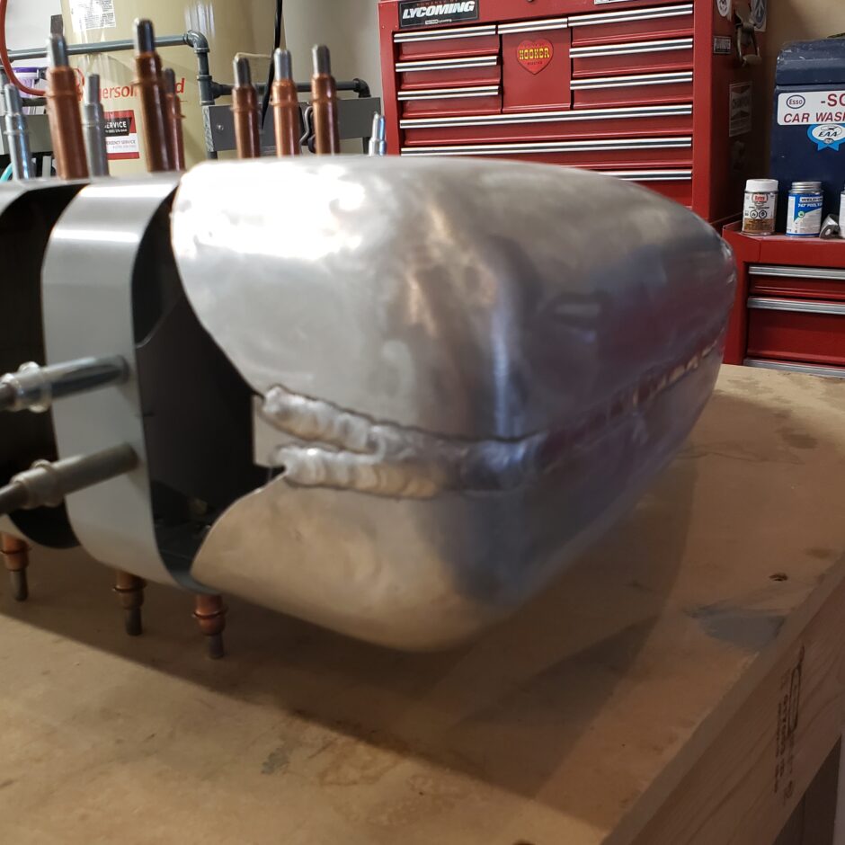
Below is a picture of the upper end of the rudder. I placed the tip on to give me some of that visual progress. As you can see, the tip fairing is aluminum. Note how it’s been fabricated in two halves, which are welded together. This fairing will need a little bit of work to get it finished, but sanding and smoothing out the weld. Again, there aren’t many other homebuilt aircraft out there with aluminum fairings.
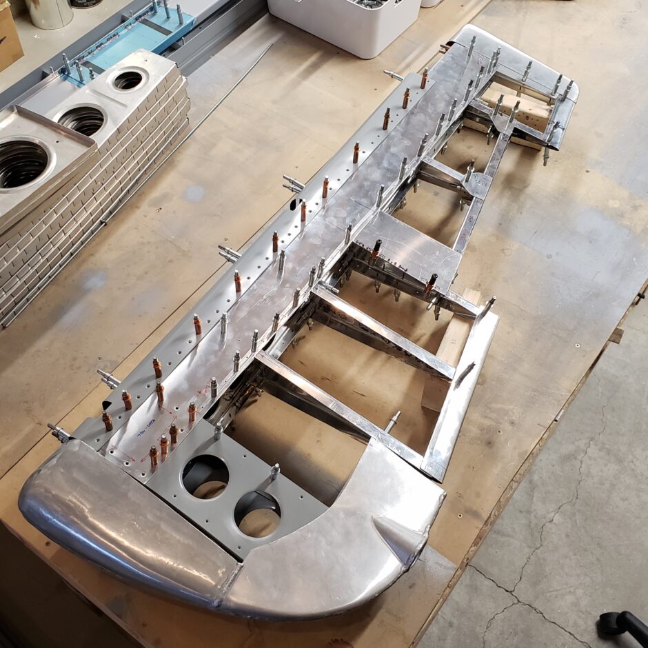
The next few pictures are some general rudder shots from different angles so you can see the assembly all in one picture.
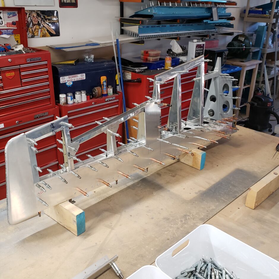
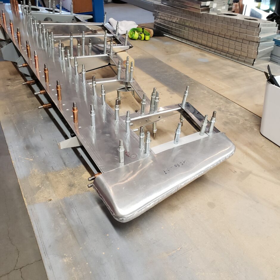
In the picture below, I have the leading edge installed as well as the lower fairing. The lower fairing is also formed out of aluminum which is quite the work of art. It’s a beautiful part for sure.
That’s all I’m able to do today. I’m super excited to keep working on the rudder. The progress is definitely inspiring. Please comment. I love to hear from my readers. Thanks again for coming along for this ride, you make my work worthwhile.
Leave a Reply