OK, fast forward about a month or so since my last post and yes, there is a lot of progress that has happened on the rudder trim tab. What I didn’t get pictures of was the drilling process of the tab to the hinge, and the hinge to the rudder.
However, as you can see from the pictures below, I’ve been working away. I also need to give a big thanks and shoutout to my buddy Garet for once again coming over and helping with the actual drilling process. Slow and steady, but we got it.
One of the issues that I was struggling with was the proper rivet spacing for the trim tab rivets. As shown in the drawing below, the rivets called for are MS20426-4. But to find spacing, I need to look elsewhere, and this will bring us to View D.
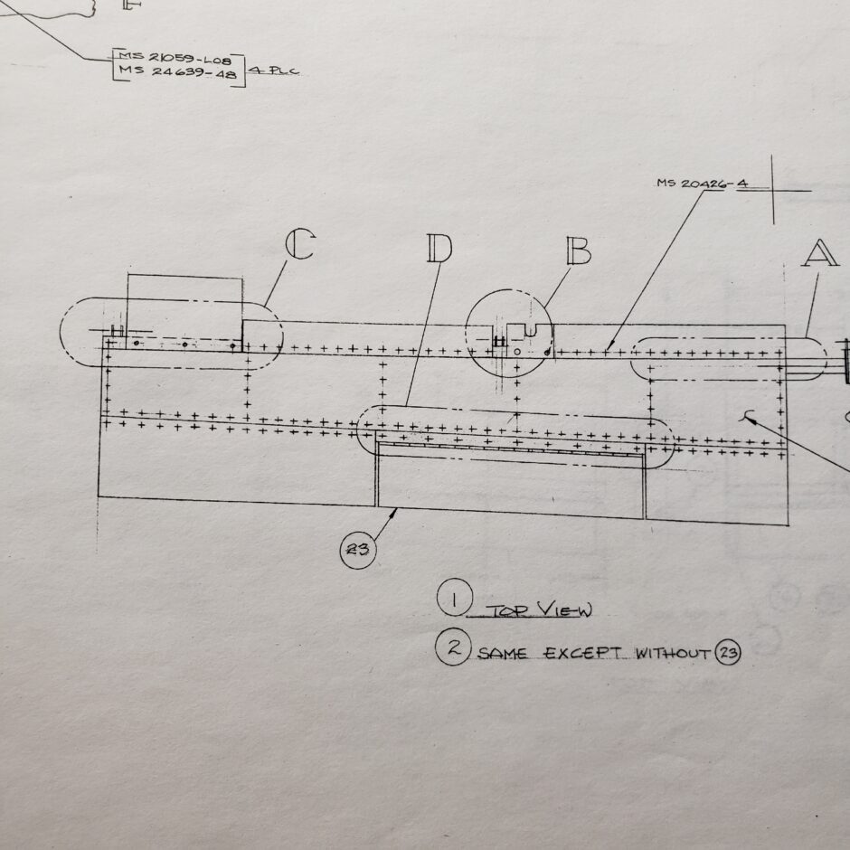
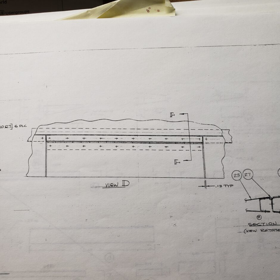
This is a good example of why the Stewart S-51 drawing are not made for scratch building this aircraft. As we can see in View D below, this just shows the dimension for the spacing between the trim tab and the rudder.
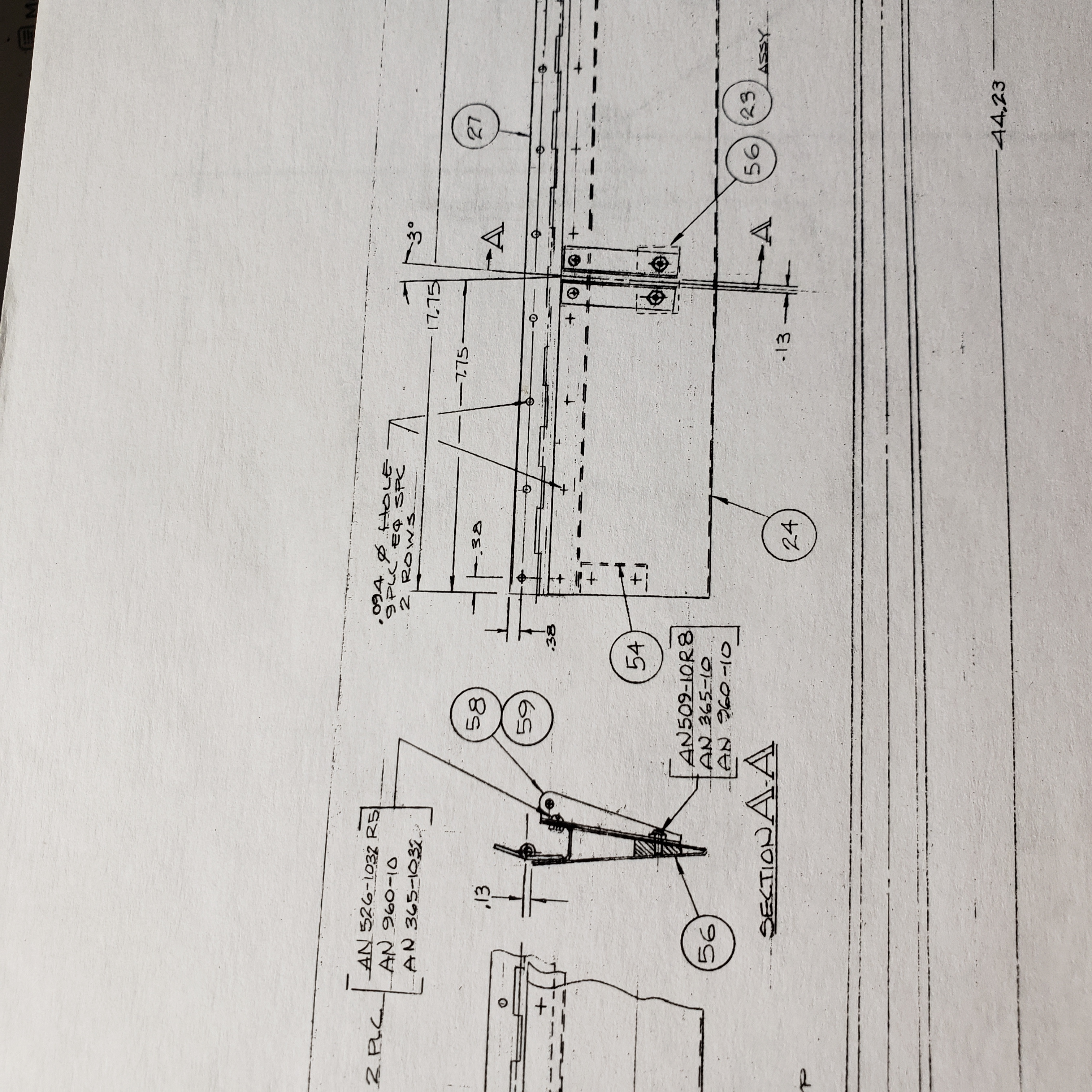
So, moving on to yet another part of the rudder drawings, here we start getting closer, in the note which states…”.94 hole, 9 PLC EQ SPC, 2 Rows”. The problem I experienced here was when I made the layout for the rivet holes that attach the rudder trim tab to the hinge, the 9 Places – Equal Spacing gave me a rivet spacing of about 2 inches or so. This I feel is much too excessive for this aircraft and the speeds to be expected.
So I reduced the rivet spacing to about 10 – 12 times the diameter of the -4 rivets. This worked out well and spread the rivet spacing between 14 rivets, as you’ll see in coming pictures.
The next fiddly bit was to get the proper amount of travel, and to also file down the trim tab skin to achieve the proper spacing in the tab cutout area.
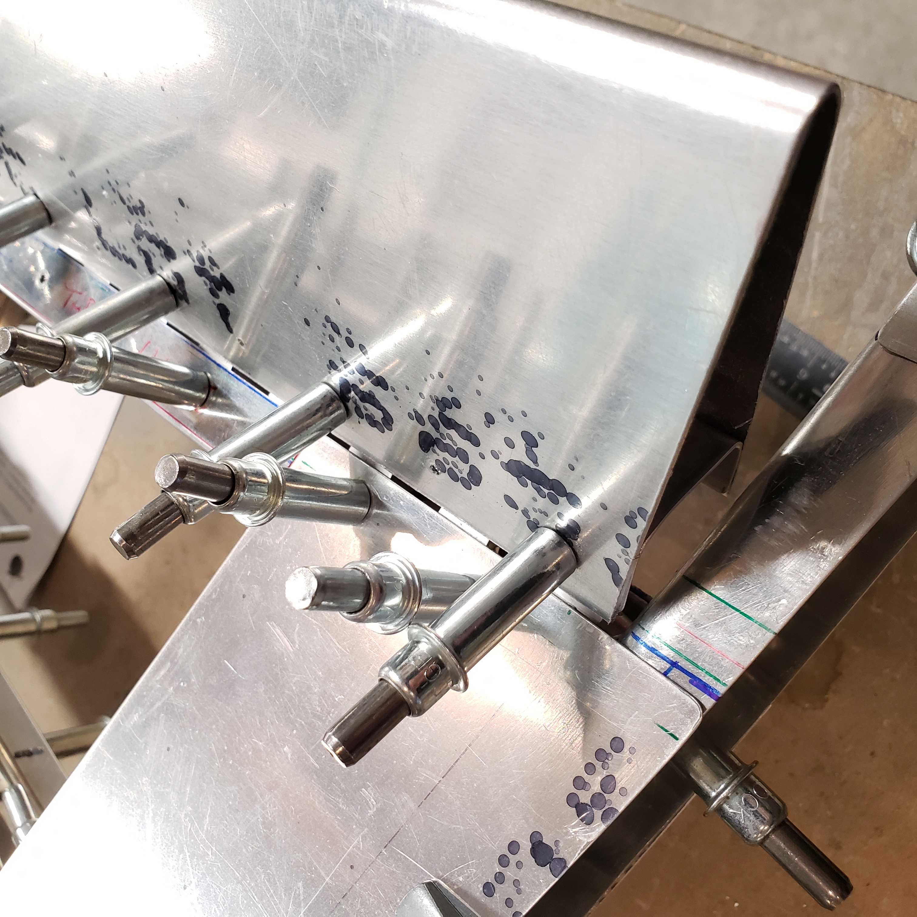
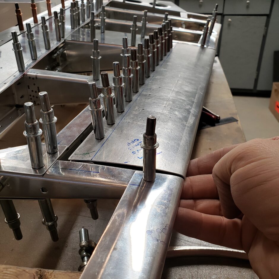
Shown below, the 0.13 gap of the trim tab cut out is coming along. I’m also happy with how well I managed to get the trailing edges to align!
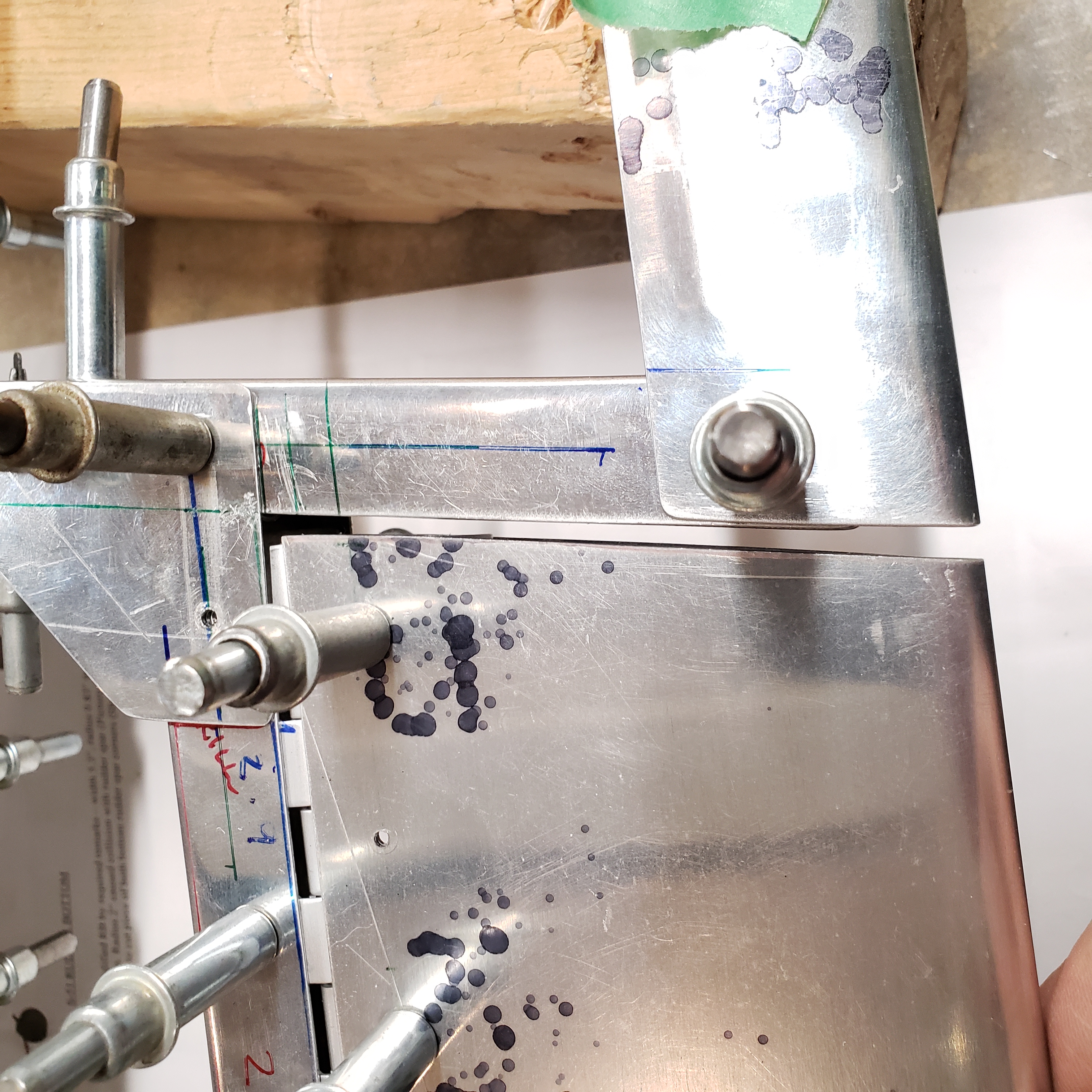
Below, the other end of the trim tab is currently in progress. To get the 0.13 dimension while trying to keep the edges all flat and square, I used my bench mounted belt sander for much of the fine tuning and slowly creeping up to the proper dimension of the trim tab skin. Also using the masking tape to hold the trailing edges in place worked well.
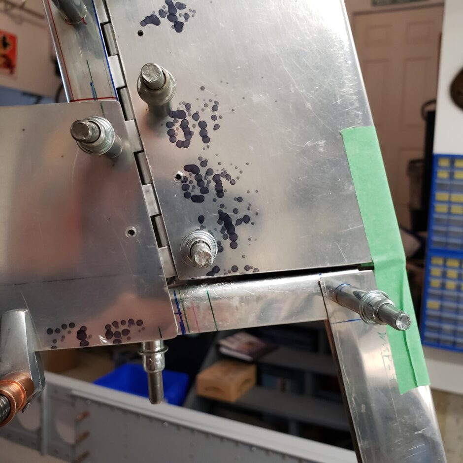
Then finally, I was able to start getting the trim tab close to being done with fitting and timing. Another interesting point to note in the picture below is how the trim tab spar is bent inward. The reason for that is to allow me to get full travel on the right side. Without bending the spar inward, it would contact and interfere with the rudder side of the tab cutout. This way, the tab just tucks itself into the opening of the cavity and then allows for full travel deflection.
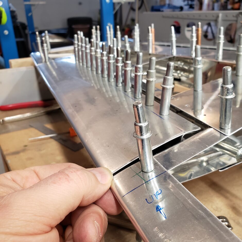
You can see this travel in the picture below.
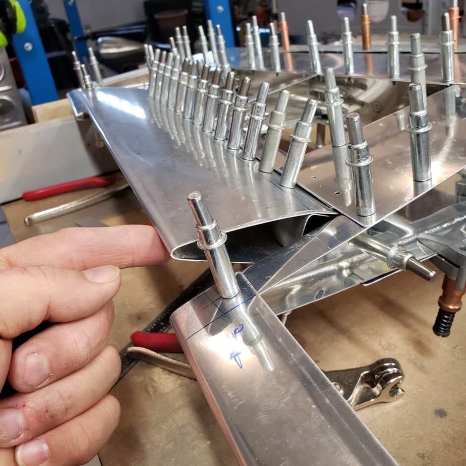
Below is a picture from the other end of the tab, looking downward.
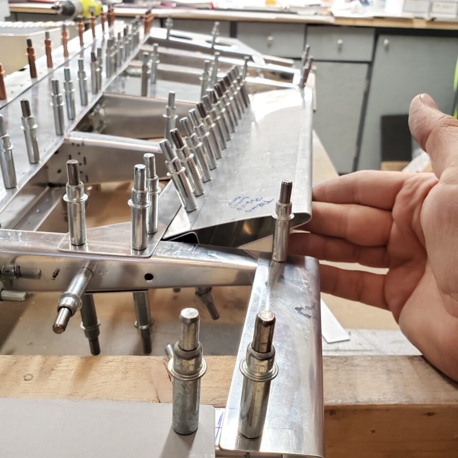
And you can see this upper end is also faired nicely and has beautiful trailing edge alignment.
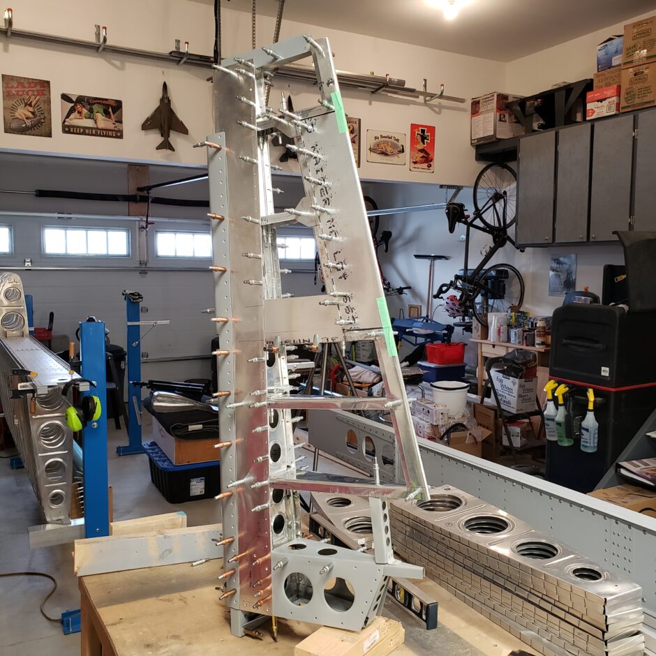
Standing the rudder up, you can see it better in the natural orientation.
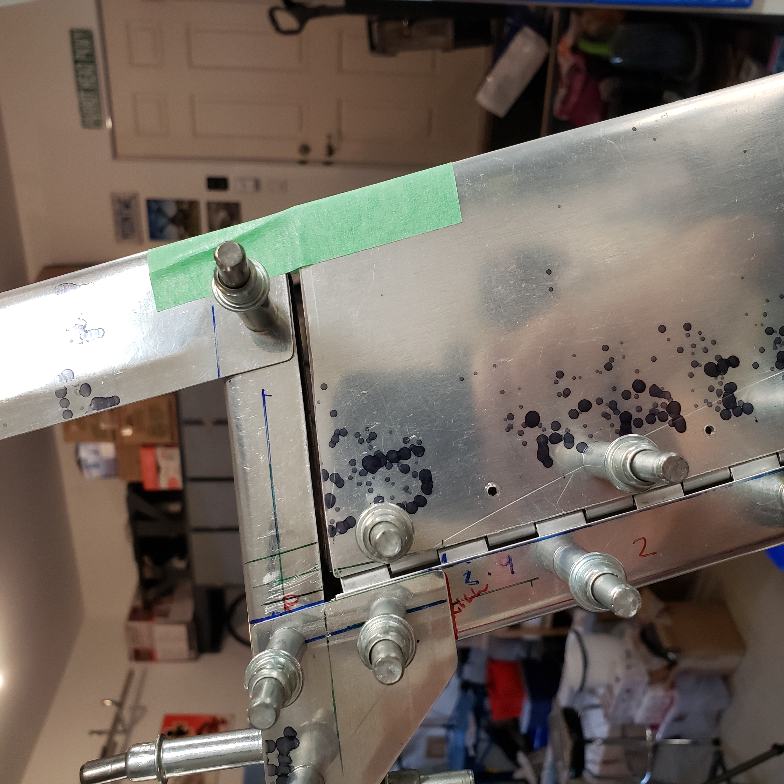
Again, here are some close up shots of the upper and lower sides of the trim tab.

That’s all for today folks! Please comment. I love to hear from my readers. Thanks again for coming along for this ride, you make my work worthwhile.
Good day!
Leave a Reply