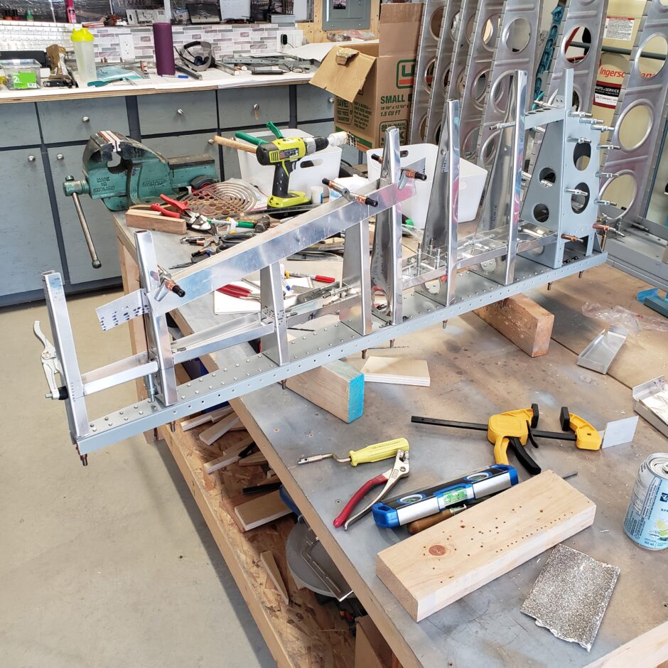
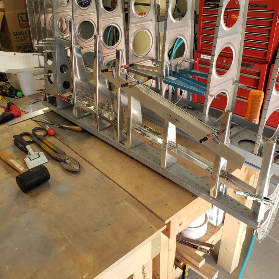
This post is continuing with my last building session in assembly of the rudder. In the image below, you can see that the ribs are getting quite a bit smaller as I’m approach the top of the rudder. It’s places like this where the cleco clamps are an amazing tool!
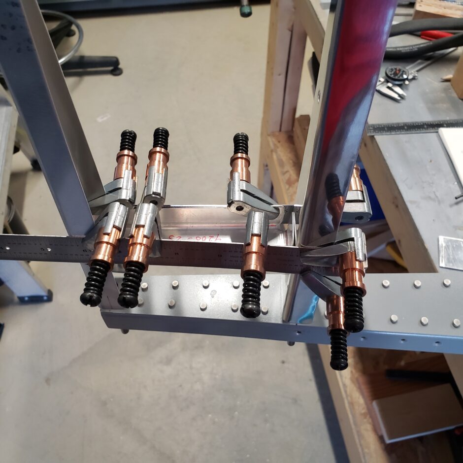
Here are some other angles of getting the 4200-23 mid-span rib in place.
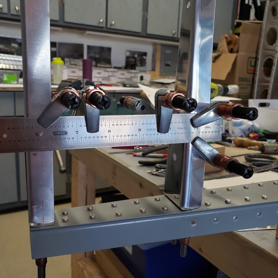
In the image below, you can see that I measured and marked (blue line) the location of the 4200-23 rib because there wasn’t enough space to get my calibrated 2×4 wooden block in as a spacer.
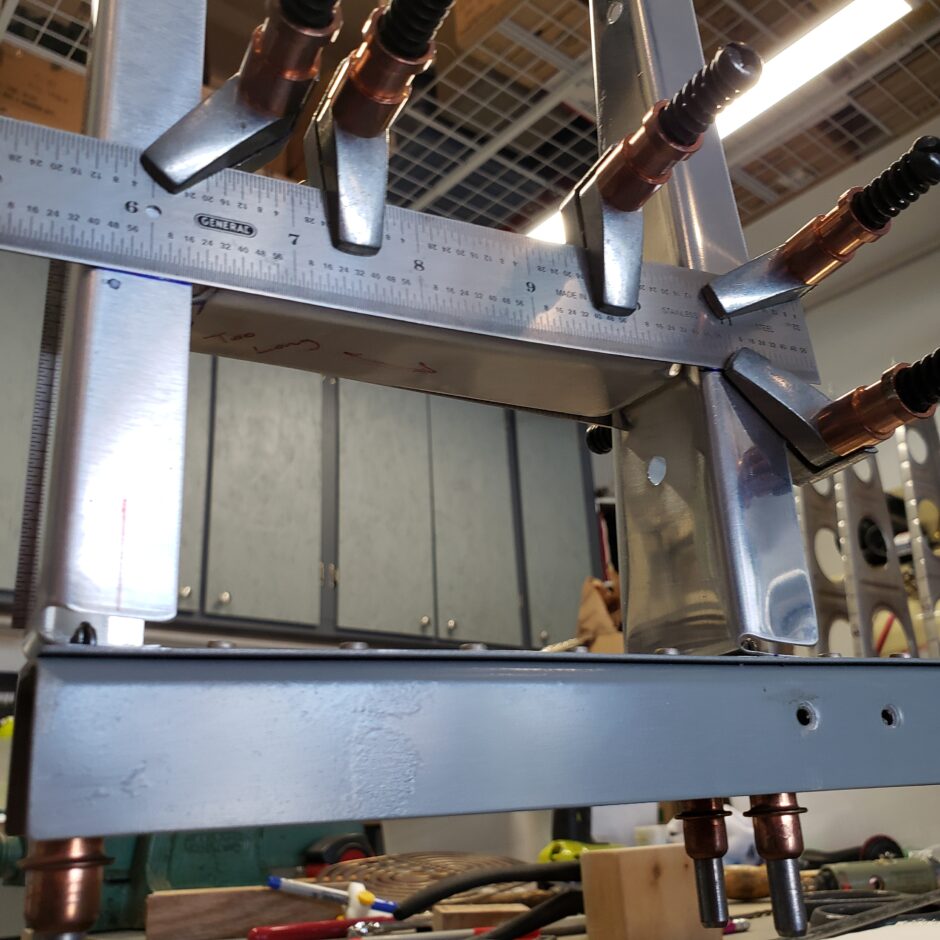
Here is another angle of the mid-span ribs getting installed. Again, between forming ribs and assembling the rudder, there is a huge assortment of tools that I’m working with…but this is the crazy reality of taking care of business!
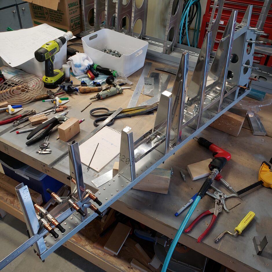
In this next picture, I’m now working at installing the trim tab spar (4200-24). It’s hard to see as I have the scarp metal strips acting as a false skin to assist in holding the parts in alignment. This sub-spar is riveted to the upper and lower ribs of the trim tab opening. Additionally, the other 2 inner ribs are also riveted to this spar rib to help tie this area together.
Forming the trailing edges
The next step in the assembly of the rudder is that I need to make some new trailing edges. This will help me start to hold the structure together as it’s really flimsy right now.
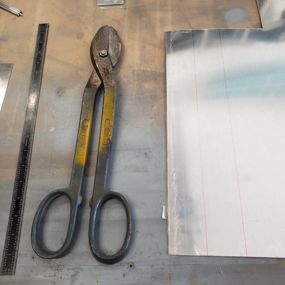
The trailing edges are formed from some 2024-T3 0.025 inch aluminum. As you can see in the picture below, I have 2 strips laid out and ready to be cut. These strips are oversized in length, as I’ll be trimming them down to the proper size in a later step.
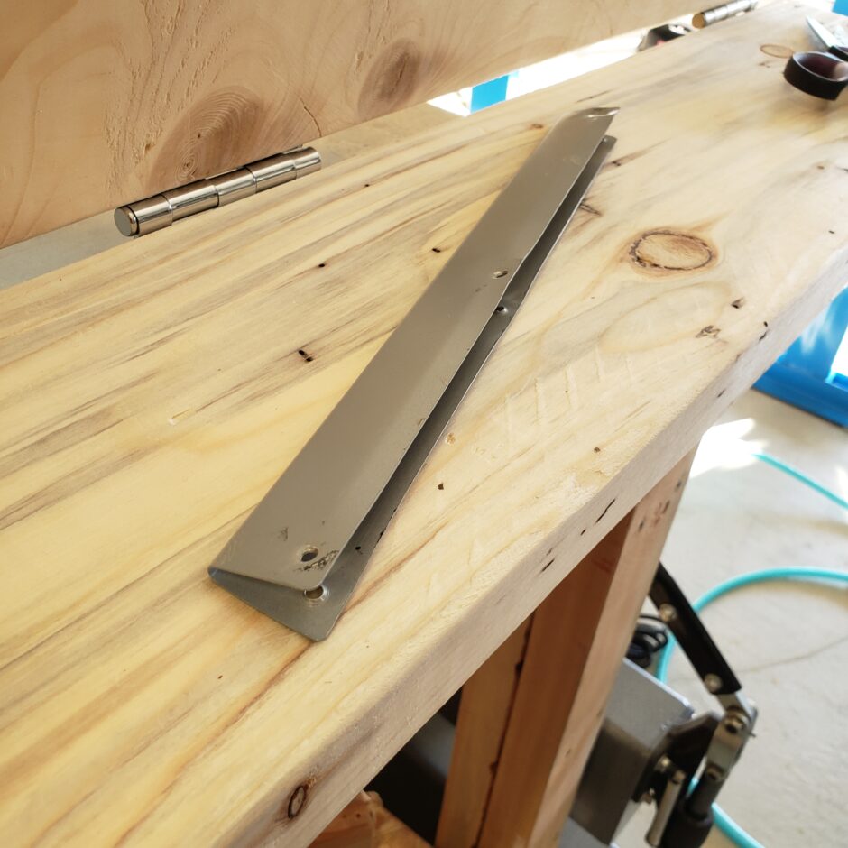
Here’s a picture of the one trailing edge segment that’s being replaced. The rivet holes are mangled and in trying to remove the rivets some of these holes developed cracks. All in all, It’s not a nice part and I’m going to make a nice new one to replace this unserviceable part.
I started by bending the flat strip in my brake to get close to a 90 degree bend as somewhere to begin. Then I worked it a bit past 90 as best I could. Additionally, I got a piece of 3/16 piano wire that I’ve taped into the radius to help me keep the round shape of the trailing edge as I bend it together.
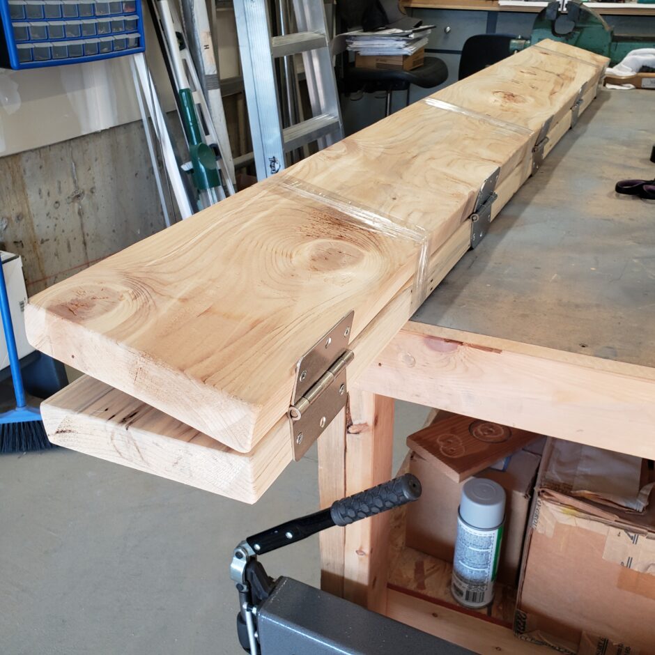
I’m using the bending tool recommended by Van’s (also used on the F1 Rocket) in forming the trailing edges of the flight control surfaces. I figure this will be a good application to use this tool again.
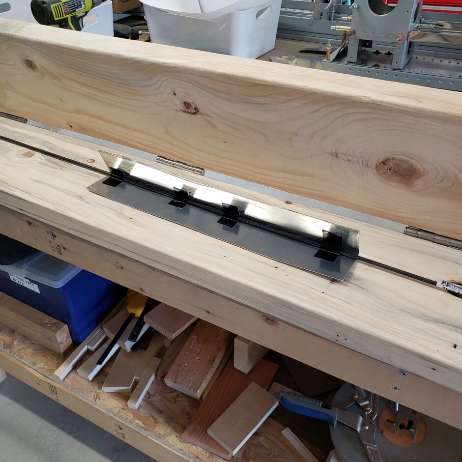
Below is a picture after the first squeeze. A bit more pressure is needed close up the gap. The required gap dimension here is 0.050 inch.
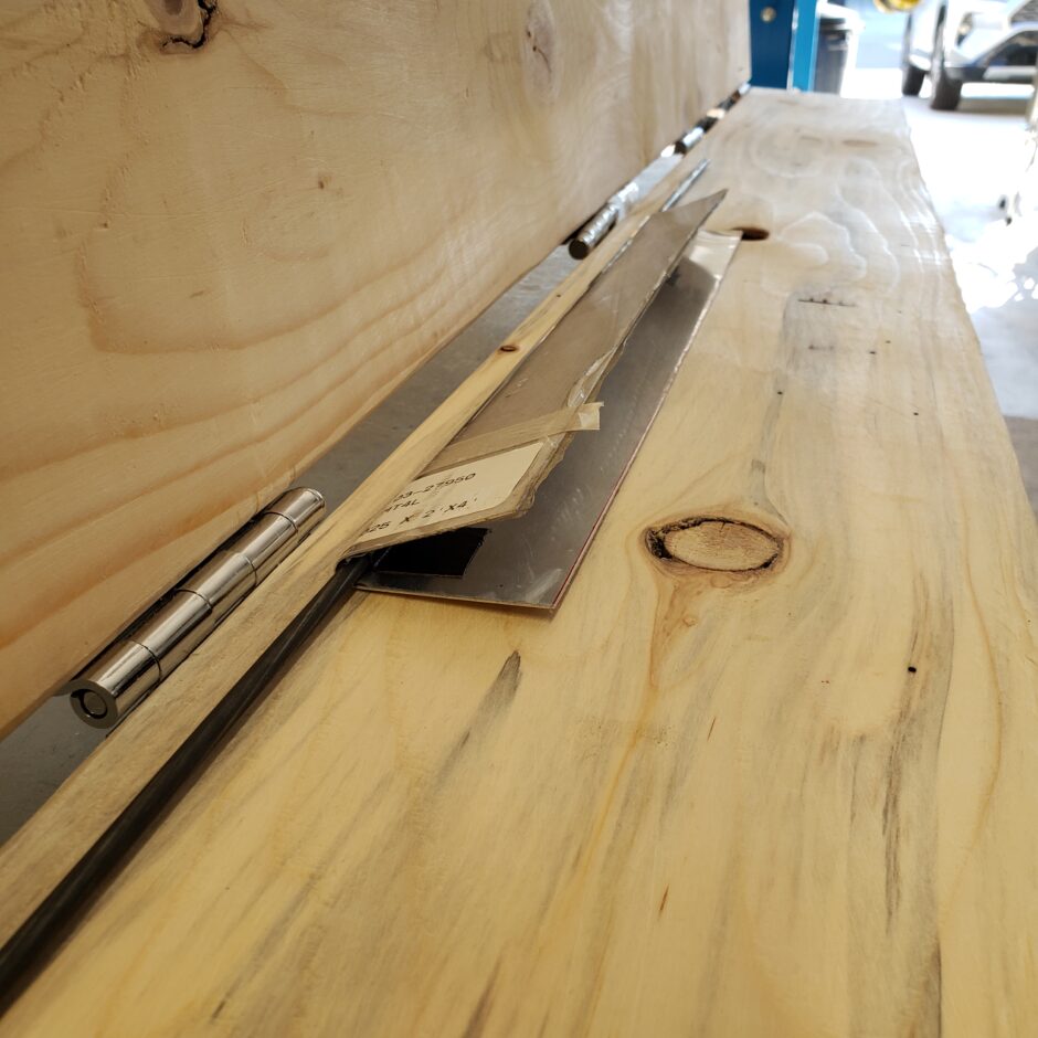
Here’s another shot of the forming tool. I used 2 x 8 boards for this one.
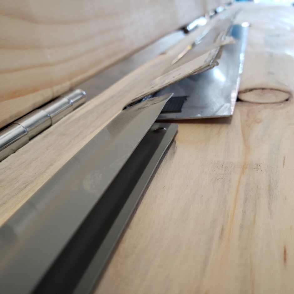
Here’s a shot after the second squeeze where I’m comparing the new part with the old. It’s pretty darn close now.
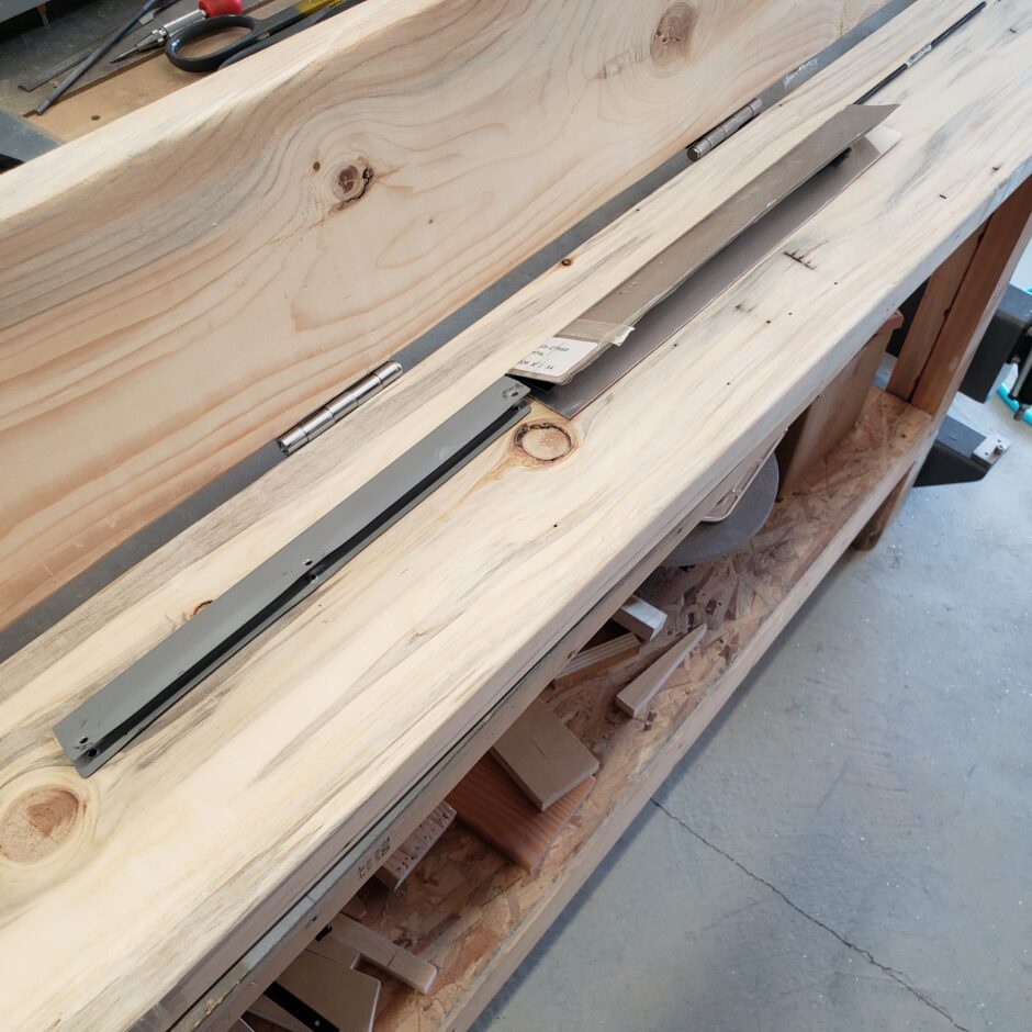
Here is a shot of the trailing edge radius. It really held up well using the piano wire. It’s got a nice gentle curve without being crimped or squished.
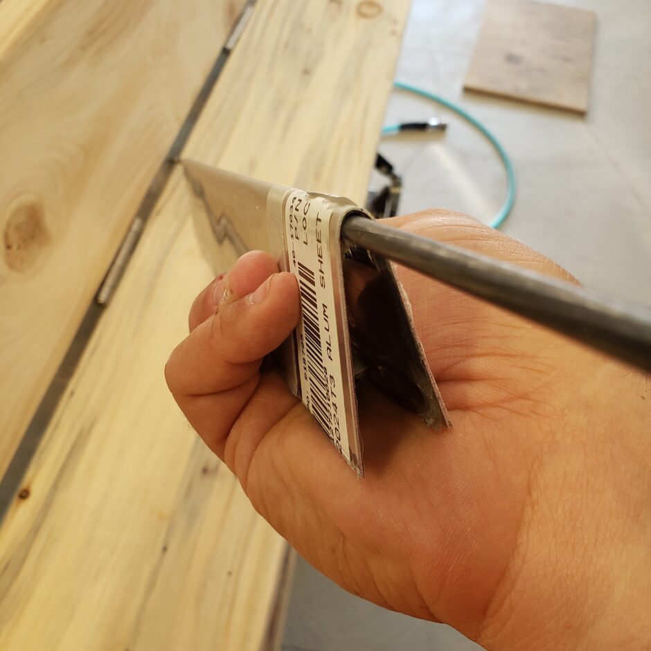
In the picture below, I’ve got the old part in place just to check alignment, checking measurements, and to see how things are fitting together.
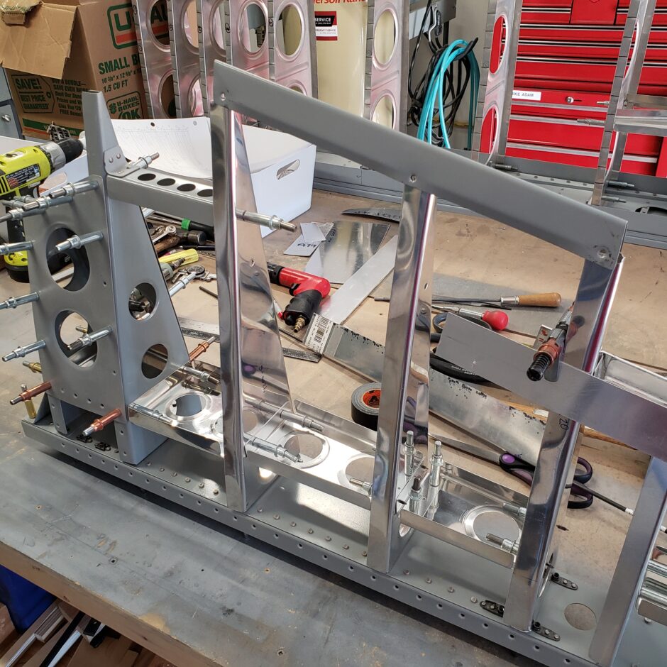
Here is the new piece installed. A few things to notice here. First, the part is significantly longer to allow for trimming. Second, it’s a bit wider as well. The first parts gave me some issues with riveting (which is why the part got mangled) as the rivets couldn’t be offset because of edge distance available. Additionally, with the rivets being very far aft on the rib, as the rib tapers, it left very little room for me to even be able to try and squeeze/buck the rivets. So with this new part being slightly wider, I’ll have more room to play with for rivet location. I’m also going to install MSP-42 rivets (pulled) rivets here to also help with the squeezing / bucking issues. The rudder will be fabric covered anyway, so using these rivets will be a minor but acceptable change.
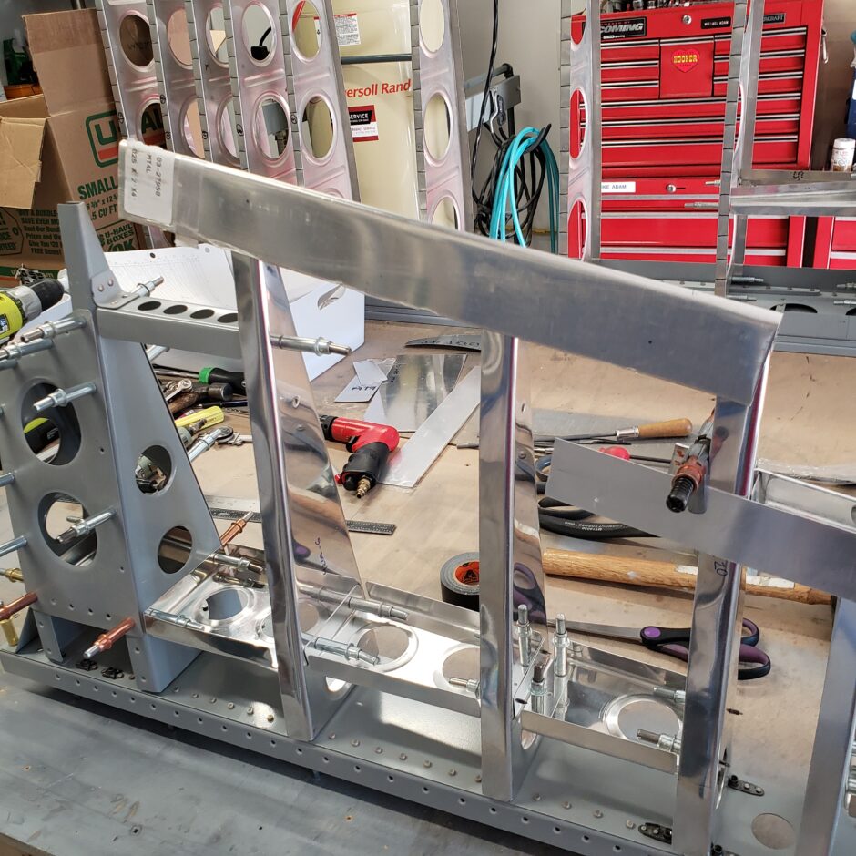
Here’s another angle of how the trailing edge is mounted on the aft end of the ribs. As you can see, even with the additional width there is still not a lot of extra edge distance to work with. Also, in this picture you can see the tab of the trim tab spar, and how that part will eventually get fastened to the rib.
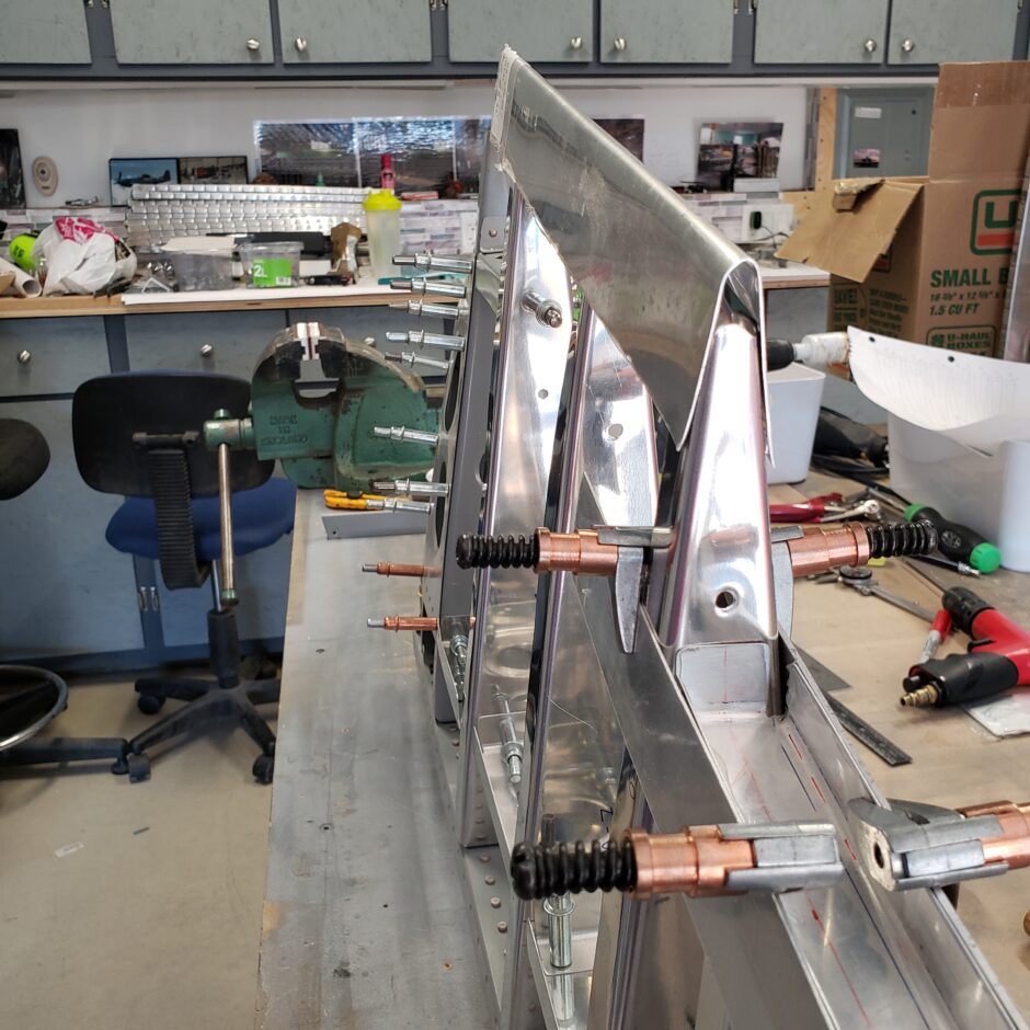
In this picture, I’m now determining the trim lines for the upper and lower ends of the edge piece.
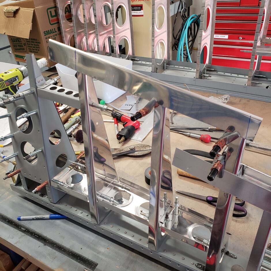
Here’s a comparison shot of the new and old parts together.
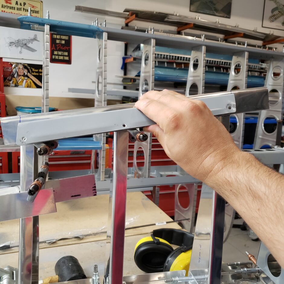
The trailing edges are slowly progressing and clamped in place. What’s not shown here is all the measuring and adjusting of the ribs to ensure the measurements are all correct, that the ribs are perpendicular to the main spar, and also how loose and wiggly this entire assembly is right now.
I’m working from the top of the rudder down (or in the picture left to right). As you can see I have a square to help me get the top rib at 90 degrees. After that I’m just working from rib to rib. I also mark the location of the rib on the trailing edge strip to help me align the parts up later (as they will eventually come on and off a few more times before I drill and locate the rivet holes).
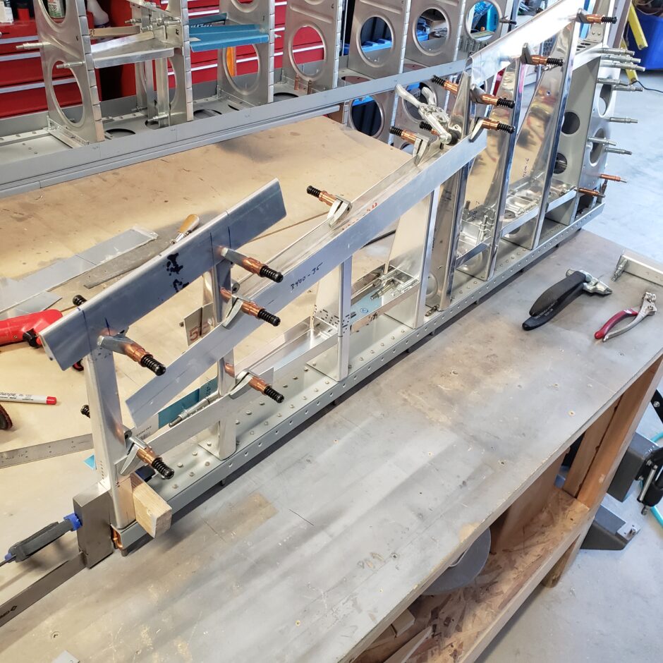
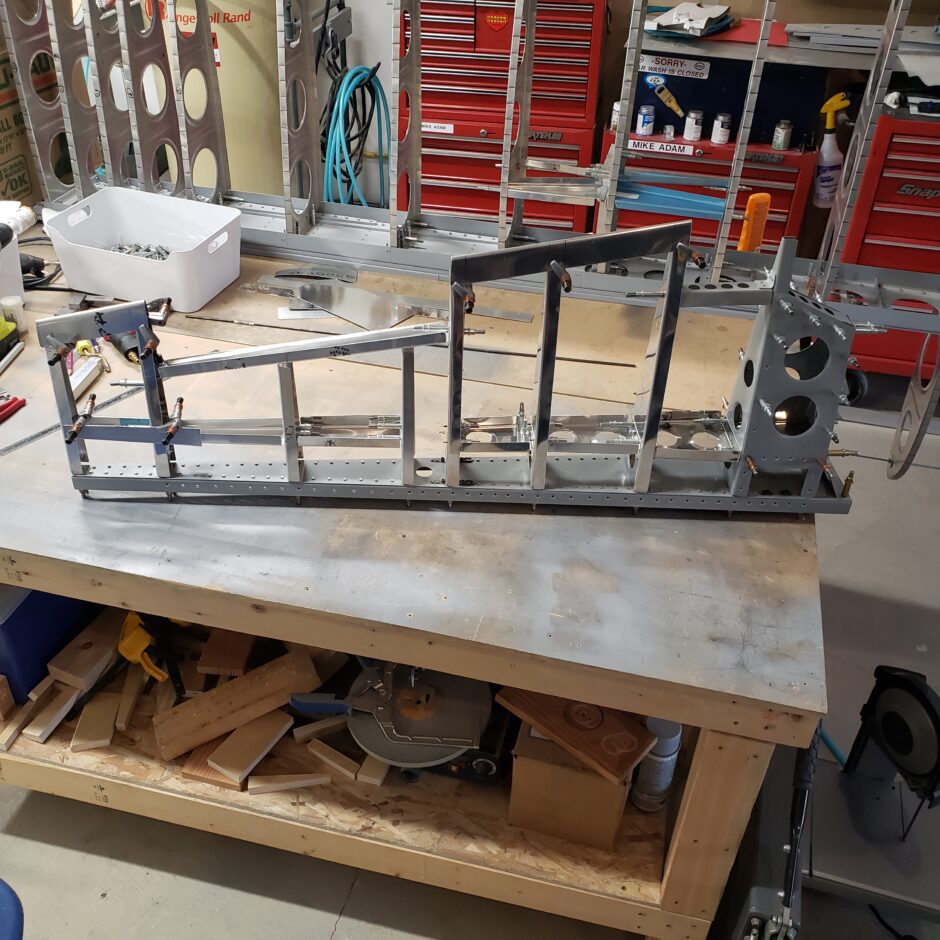
In this last picture, this is where I’m going to leave my progress for today. It’s finally starting to look like a rudder! I’m super happy with the how the work is progressing. I’m not quite certain enough yet to drill the trailing edges. I’ll do some more measuring and hopefully in my next building session I can tackle that issue.
Please comment. I love to hear from my readers. Thanks again for coming along for this ride, you make my work worthwhile.
Leave a Reply